Whether you are new to the industry or are well seasoned and want to review some of the basic information that you learned in the past, these courses and lessons will clearly outline what you are looking for. “Power Systems Electric” is On-Line training that bridges the gaps between textbook theories and practical power systems experience. As a retired electrical engineer who has gone through the experience of developing a career in electrical power systems, I know how frustrating it can be to try and find the answers, so I put together these courses that I feel would have been a major help to me in my development. I have also taken suggestions from students of what they would like to see in addition to these courses which I have given live in person.
Basic Electrical Learning
For those new to the industry, there is a beginner’s group of courses that cover the “Fundamentals of Electricity” including DC and AC Circuit Analysis. These lessons examine such basics as Ohm’s Law, Series, and Parallel Circuits. The first, and perhaps most important, relationship between current, voltage, and impedance, “Ohm’s Law”, and its relevance to Series and Parallel Circuits. Subsequently, this will lead to the development of Kirchhoff’s Laws as they help to further analyze Network Analysis & Metering Circuits.
Conductors and Insulators are investigated along with their connected components, Capacitors, Inductors, and how they are influenced by Electromagnetism.
Alternating Current (AC – an electric current that periodically reverses direction) is the form in which electric power is delivered to businesses and residences, and it is the form of electrical energy that consumers typically use when they plug kitchen appliances, televisions, fans, and electric lamps into a wall socket.
The abbreviations AC and DC are often used to mean simply alternating and direct, as they are applied to current or voltage.
These AC courses deal specifically with sinusoidal waveforms and will provide the student with the basic understanding of working with circuits involving Alternating Current, which includes sinusoidal waveforms, vectors & phasors, reactance & impedance of R,L,C circuits, as they relate to the basic laws and theorems of electricity. This includes working with AC Power, Power Factor, Resonance, Complex Numbers, Reactance, and Impedance
Advanced Electrical Learning
These Courses involve subjects such as “Short Circuit Analysis for HV Three-Phase Systems” which introduces the student to the basic concepts of fault studies on a high voltage three-phase system. System modeling is then used in order to aid in this process, with the ability to move between asymmetrical and symmetrical systems. With hey Searle and extensive study of “Per Phase” & “Per Unit” methodologies system faults are analyzed with the use of symmetrical components.
“A Per-Unit System” is the expression of system quantities as fractions of a defined base unit quantity. Calculations are simplified because quantities expressed as per unit do not change when they are referred from one side of a transformer to the other.
In these courses, you will learn exactly what Per Unit Analysis is, the main advantages of using it, how manufacturers of equipment use and rate their products, and the technique of converting to and from the Per Unit system.
Several examples of working with Per Unit are demonstrated in this crisp clear presentation. When you finish you will have a though understanding of this subject.
It is important for all power engineers and technicians to be familiar with the concept of Per Unit as it is being used and referred to every day in power flow, short circuit evaluation, and motor starting studies.
The method of “Symmetrical Components” is used to simplify asymmetrical three-phase voltages and current analysis by converting the unbalanced system into two sets of balanced phasors and a set of single-phase phasors, or symmetrical components. These sets of phasors are called the positive, negative, and zero sequence components.
An understanding of this method is essential for the understanding of fault analysis and modern-day protection schemes. These courses will provide you with the knowledge to comprehend the concept and how it is applied.
Supplemental Electrical Lessons
In all power electrical analyses, the student will encounter special Trigonometric and Mathematical identities and equations. This site contains special supplemental lessons that zero in on those identities and equations. For example, there are lessons that take you from the “Fundamentals of Trigonometry” to the more sophisticated requirements in electrical engineering. As you work and study in electrical engineering you are going to run into proofs and equations that are based on trigonometry. A good example of this is when studying AC current, voltage, and impedance calculations, phasors or vectors are used and combined mathematically. Further adventures into complex power will also require a knowledge of trig functions and identities. As a student of this course, you will be introduced to these or at least re-introduced to these that may have been long since forgotten.
In mathematics, “The Derivative of a Function” of a real variable measures the sensitivity to change of the function value (output value) with respect to a change in its argument (input value). Derivatives are a fundamental tool of calculus. For example, the derivative of the position of a moving object with respect to time is the object’s velocity: this measures how quickly the position of the object changes when time advances.
Specialized Electrical Lessons
Specialized lessons include the “Protection & Control(P & C)” principles of high voltage stations. HV Bus Differential Protection is studied along with restrictions due to CT saturation & mismatch and its solution, “Restraint Differential Protection”.
High Voltage Circuit Breakers are examined as to the various Types (Oil, Vacuum, Air Blast, SF6), their Controls as well as the introduction of potential transformers & current transformers, and their use in conjunction with the relevant instruments such as ammeters, voltmeters, watt meters, and energy meters.
Other lessons include the study of “Transformers” including core construction along with losses, cooling, and mitigation techniques. Three-phase transformer configurations are studied along with harmonic distortion, CT saturation, and on-load tap-changer problems and how these problems are dealt with. Over-current and restraint differential transformer protection is developed along with a look at some examples of ” Old School relays” as well as modern IDE (intelligent Electrical Devices) relays.
Transformer Connections: (Y – Y; Delta – Delta; Y – Delta; Delta – Y & Y – Zag Zig) are examined along with Transformer Clock System Vector Nomenclature.
Lastly, there is a special section dedicated to “Single and Three-Phase Metering“, including old analog and new digital kilowatt-hour meters.
Conclusion
Regardless of whether or not you are new to the industrial power system, you’ll find what you’re looking for on this site in the way of training. In order to review or select any of these courses, left-click on any of the blue highlighted hyperlinked words of this posting or on “14 Courses Available” from the top menu of the landing page. All of the courses have a free introduction

As a bonus and in the way of a thank you, for your interest in PSPT’s WEB (and Blog) page, I’m making available my 50-page “Electrical Power” crib sheets. These were prepared for use with my courses that are available on this site. There is one section associated with each course and is extremely valuable while viewing the course, as well as a recall of the pertinent formulas and information after the fact. The contained information is also useful during any technical career as a quick reference from time to time. Simply click here or on the picture to the right to be taken to where you can download this item.


Blog # 19 - Logic Gates (5 of 8 in the Series) Electrical Wiring Diagrams
/
All digital electronic devices employ switches that perform specific logical operations. These switches, called logic gates, can have anywhere from one to several inputs and (usually) a single output. Logic devices have two states, represented by the digits 0 and 1. The 0 digit is normally called “low” and the 1 digit is called “high.”

Gates are used in everyday (IED’s), Intelligent Electronic Devices, such as computers, microprocessors, smart house devices, metering and relays just to mention a few.

A binary quantity is one that can take on only 2 states. The above is a binary arrangement…a switch in series with a power source and a light. The switch can be open or closed. the light can be either off, or on. We can now assign a binary number to the switch and the light. For the light, On, = 1 or Off = 0. For the switch, Closed = 1 or Open = 0.
In order to analyze these binary arrangements we devise, a truth table.

This is a binary arrangement that has two switches in series with a power source and a light. Either switch can be, open, or closed...the light will be either, off, or on. As before we can now assign a binary number to the light and the switch.
For the light On = 1, Off = 0. For the switches Closed = 1, Open = 0.
And in order to analyze these binary arrangements we devise a truth table. The two switches form what is known in logic gate terms as, an “AND” gate. We state its logic in the equation L = S1 AND S2.

Here is another binary arrangement with two switches in parallel, which generates this truth table.
The two switches form what is known in logic gate terms, as an “OR” gate.
We state it logically in the equation, L = S1 OR S2.

Here is yet another binary arrangement with three switches in series with the truth table shown.
The three switches form what is known in logic gate terms as an “AND” gate.
We state its logic in the equatio, L = S1 AND S2 AND S3.

Here is yet another binary arrangement with three switches, this time in parallel. Which generates the truth table shown above.
The three switches form what is known in logic gate terms as an “OR” gate.
We state it logically in the equation L = S1 OR S2 OR S3.

Here is yet another binary arrangement with three switches, this time in a combo, series-parallel arrangement.
Which generates the truth table as above.
The logic of these three switches can be described by the equation
L = S1 AND (S2 or S3)

In most solid-state systems (computers etc.), the logic is set up in terms of voltage levels.
0 Volts = “low", logic level (0),
5 Volts = “high", logic level (1).
If we apply 5 volts to the input of the transistor in this circuit, the transistor is in a state of saturation by virtue of the applied input voltage (5 volts) through the two-position switch. Because its saturated, the transistor drops very little voltage between the collector and emitter, resulting in an output voltage of (practically) 0 volts.
If we were using this circuit to represent binary bits, we would say that the input signal is a binary ”1” and that the output signal is a binary ”0.” Any voltage close to the full supply voltage (measured in reference to ground, of course) is considered a ”1” and a lack of voltage is considered a ”0.” Alternative terms for these voltage levels are high, (the same as a binary ”1”, and low (the same as a binary ”0”). A general term for the representation of a binary bit by a circuit voltage is, logic level.

Moving the switch to the other position, we apply a binary ”0” to the input and receive a binary ”1” at the output, putting the transistor into cut-off. What we’ve created here with a single transistor, is a circuit generally known as a solid-state logic gate or simply a gate. A gate is a special type of amplifier circuit, designed to accept and generate voltage signals corresponding to binary 1’s and 0’s. As such, gates are not intended to be used for amplifying analog signals. Used together, multiple gates may be applied to the task of binary number storage, (memory circuits) or, manipulation, (computer circuits), each gate’s output representing one bit of a multi-bit binary number. Just how this is done is a subject for further study. Right now, it is important to focus on the operation of individual gates.

The gate shown here with the single transistor is known as an inverter, or a NOT gate because its output is the exact opposite of the digital input signal. For convenience, gate circuits are generally represented by their own symbols rather than by their circuit diagrams of transistors and resistors. The above is the symbol for a not gate.

Remember our series switches circuit. We can now represent this system by the standard 2-input AND gate symbol, with, the same truth table as the two series switch version.

Remember our three series switches circuit. We can now represent this system by the standard, 3-input AND gate symbol with the truth table which is identical to the three series switch version.

What this truth table means in practical terms is shown in the following sequence of illustrations.
With the 2-input and gate subjected to all possibilities of input logic levels. A Light-Emitting Diode provides a visual indication of the output logic level:
For an Input of 0 0, the output is 0.
For an Input of 1 0, the output is 0.
For an Input of 0 1, the output is 0.
For an Input of 1 1, the output is 1, red light on.
It is only with all inputs raised to a ”high” logic level that the AND gate’s output goes ”high,” thus energizing the LED for only one out of the four input combination states.

A variation on the idea of the AND gate is called the NAND gate. The word, ”NAND” is a verbal contraction of the words NOT and AND. Essentially, a NAND gate behaves the same as an AND, gate with a NOT, (inverter) gate, connected to the output terminal. To symbolize this output signal inversion, the NAND gate symbol has a bubble on the output line. The truth table for a NAND gate is as one might expect, exactly opposite to that of an AND gate. As with AND gates, NAND gates, are made with more than two inputs. In such cases the same general principle applies:
The output will be, ”low”, (0), if and only if all inputs are ”high”, (1).
If any input is ”low”, (0), the output will go ”high”, (1).

Our next gate to investigate is the OR gate. It can have any number of inputs. For example, the one on the left has two inputs and another one on the right has three. The truth tables of each are depicted here…These are called OR gates, because:
The output will be ”low”, (0), if and only if all inputs are ”low”, (0).
The output will be ”high”, (1), if any of the inputs are ”high”, (1).

The following sequence of illustrations demonstrates the OR gate’s function, with the 2 inputs experiencing all possible logic levels. A Light-Emitting Diode provides a visual indication of the gate’s output logic levels:
For an Input of 0 0, the output is 0.
For an Input of 1 0, the output is 1, red light on.
For an Input of 0 1, the output is 1, red light on.
For an Input of 1 1, the output is 1, red light on.
A condition of any input being raised to a ”high” logic level makes the OR gate’s output go ”high” logic level thus energizing the LED for three out of the four input combination states.

As you might have suspected, there exists an inverted OR gate known as the NOR gate, which is an OR gate with its output inverted just like a NAND gate is an AND gate with an inverted output. NOR gates, like all the other multiple-input gates seen thus far, can be manufactured with more than two inputs. Still, the same logical principle applies.
The output goes ”low”, (0) if any of the inputs are made ”high”, (1).
The output is ”high”, (1), only when all inputs are ”low”, (0).

Another gated function is the Negative AND gate. The Negative AND gate, functions the same as an AND gate, with all its inputs inverted, (connected through NOT gates). In keeping with the standard gate symbol convention, these inverted inputs can be signified by bubbles. Contrary to most peoples’ first instinct, the logical behavior of a Negative AND gate is not the same as a NAND gate. Its truth table, actually, is identical to a NOR gate.
The output goes ”low”, (0), if any of the inputs are made ”high”, (1).
The output is ”high”, (1), only when all inputs are ”low”, (0).

Following the same pattern, a Negative, OR gate functions the same as an OR gate with all its inputs inverted. In keeping with the standard gate symbol convention, these inverted inputs can be signified by bubbles.
This function can also be written as these equivalent gate circuits…the behavior and truth table of a Negative OR gate is the same as for a NAND gate.

The Exclusive OR gate.
The last six gate types are all fairly direct variations on three basic functions. AND, OR, and NOT. The Exclusive OR gate, however, is something quite different. The Exclusive OR gate’s output is a ”high”, (1), if the inputs are at different logic levels, either 0 and 1, or 1 and 0. Conversely, the output is a ”low”, (0), if the inputs are at the same logic levels.
The Exclusive,-OR gate (sometimes called an XOR gate) has both a symbol and a truth table pattern that is unique.

The equivalent circuit to the exclusive OR gate shown above has the same truth table as an exclusive or gate, therefore this equivalent circuit can be replaced by a single 2-import OR gate. Work it out it's a good exercise.

Finally, our last gate for analysis is the Exclusive-NOR gate, otherwise known as the XNOR gate. It is equivalent to an Exclusive-OR gate with an inverted output. The truth table for this gate is exactly opposite as for the Exclusive,-OR gate. As indicated by the truth table, the purpose of an Exclusive-NOR gate is:
To Output a ”high”, (1), logic level whenever both inputs are at the same logic levels, (either 0 0, or 1 1).
Also to Output a “low”, (0), logic level if the inputs are different.

Gate universality.
NAND and NOR gates possess a special property. They are universal. That is, given enough gates, either type of gate is able to mimic the operation of any other gate type. The ability for a single gate type to be able to mimic any other gate type is one enjoyed only by the NAND and the NOR. In fact, digital control systems have been designed around nothing but NAND or NOR gates, all the necessary logic functions being derived from collections of interconnected NAND’s or, NOR’s.
Let’s have a look at this universality and see how all the basic gate types may be formed using only NAND’s or only NOR’s. As you can see, there are two ways to use a NAND gate as an inverter, and two ways to use a, NOR gate, as an inverter.

Constructing the AND function.
To make the AND function from NAND gates, all that is needed is an inverter, (a NOT) on the output of a NAND gate. This extra inversion ”cancels out” the first N in NAND, leaving the AND function.
It takes a little more work to wrestle the same functionality out of NOR gates, but it can be done by running all of the inputs to a NOR gate, thru not gates, which are NOR gates made to function as NOT gates.

We can Construct the NAND function using NOR gates. To make a NOR gate perform the NAND function, we must invert all inputs to the NOR gate, as well as the NOR gate’s output.

Constructing the OR function.
Inverting the output of a NOR gate, (with another NOR gate connected as an inverter), results in the OR function. The NAND gate, on the other hand, requires an inversion of all inputs to mimic the, OR function, just as we needed to invert all inputs of a NOR gate to obtain the AND function. Remember that inversion of all inputs to a gate results in changing that gate’s essential function. AND to OR (or vice versa), plus an inverted output. Thus, with all inputs inverted, a NAND behaves as an OR.
A NOR behaves as an AND.
An AND behaves as a NOR and,
An OR behaves as a NAND.

Constructing the NOR function.
Much the same as the procedure for making a NOR gate behave as a NAND, we must invert all inputs and the output to make a NAND gate function as a NOR.
Blog # 18 - More Component Symbols - (4 of 8 in the Series) Electrical Wiring Diagrams
/
More Electrical Component Symbols

A transformer is made up of multiple inductors, with the coil turns interspersed, or wownd around different parts of a single core. The symbol for a basic air-core transformer looks like this. Two air-core coils drawn back-to-back. A transformer has the ability to transfer AC energy from one circuit to another at the same frequency. Because transformers are made by combining inductors, the schematic symbols are similar.
Here we see some transformers that contain iron cores. The ones at A and B have solid or laminated cores, the ones at C and D have powdered cores.

Most electrical power, when produced at power plants, is produced as three-phase AC voltage. Electrical power is also transmitted in the form of three-phase voltage, over long-distance power-transmission lines.
At its destination, three-phase voltage can be changed into three separate single-phase voltages for distribution into the residential areas. Although single-phase systems are used mainly for residential power distribution systems, there are some industrial and commercial applications of single-phase systems. Single-phase power distribution usually originates from three-phase power lines, so electrical power systems are capable of supplying both three-phase and single-phase loads from the same power lines. This 3-Phase schematic shows a typical power distribution system from the power station, or (source) to the various single-phase and three-phase loads that are connected to the system.
The above drawing shows a single-phase power distribution system, at (A) is a Single-phase, two-wire system, at (B) is a Single-phase, three-wire system (taken from two hotlines) and at (C) is a Single-phase, three-wire system (taken from one hot line and one grounded neutral).
Single-phase systems can be of two major types. a single-phase two-wire system, which is shown in “A”, (the top diagram), or a single-phase, three-wire system, which is shown in “B” and “C”, (the middle and bottom diagrams). These systems shown here us 10 KVA, 20 KVA, and 30 KVA transformers whose secondary produces single-phase voltages, such as 120 and 240 volts.
In early residential distribution systems, single-phase two-wire system were the type most used to provide 120-volt service. However, as appliance power requirements increased, the need for a dual-voltage system was evident.
To meet the demand for more residential power, the single-phase three-wire system is now used. A home service entrance can be supplied with 120 240-volt energy by the methods shown in “B”, and “C”, (the center and bottom diagrams). Each of these systems is derived from a three-phase power line. The single-phase three-wire system has two hotlines and a neutral line. The hotlines, whose insulation is usually black and red, are connected to the outer terminals of the transformer secondary windings. The neutral line (the white insulated wire) is connected to the center tap of the distribution transformer. Thus, from neutral to either hotline, is 120 volts that may be obtained and used mainly for lighting and low-power requirements.
All of the aforementioned information is given in this one concise three phase schematic drawing.

Three phases, and transformers…You'll notice that I did not write “Three Phase Transformers” because transformers are not inherently three phase in themselves, but it is how they react when connected to the system.
In order to verify what I just said, let's start with just one transformer. We will call it a single-phase transformer. Now let's draw two more transformers. So far what we have are three single transformers, independent of each other.
Sometimes, it is more efficient to have these three transformers, on the same core which is usually indicated as you see here. This does not change the fact that we still have three transformers that until we make connections to them, are still independent of each other. I am not going to go into any further detail on the makeup or construction of transformers, because that is another course. What we are interested in here is how to interpret them on an electrical drawing.
Transformers serve many functions, however, let's just stick to their ability to step the voltage up or down, depending on where it is in the system. So we designate the primary and secondary's of transformers according to where the power is being delivered from. Power is always delivered to the primary side of the transformer, and it is always delivered from the secondary of the transformer.
I am now going to connect the bottom side of each winding on the primary side of the transformer, ground that connection, and designate it as neutral or N. The top side of the winding I'm going to connect to a balanced three-phase power system, that is designated, “R,” Red, “W,” White, and “B,” Blue. This is known as a “Y” connection and is designated as such on drawings and nameplate data as shown here. The fact that the neutral is grounded is indicated with a grounding symbol coming from the center point of the Y. What you see here is exactly what you would find on a three-phase schematic drawing, although the secondary connections haven't been shown, I will deal with that shortly. A very important point to note here is that we are dealing with AC voltages on the primary. Even though we are connected to a three-phase source each of the transformers is only going to see one AC voltage and will handle it as such. This means it will either step that voltage up or down, but it will be in phase with that one voltage. Because it is a balanced system, the voltages are equal in magnitude and 120° apart… which I have indicated with the colored vectors or phasors However, because we have connected the bottoms of the primary windings together, the phasor tails form a neutral. This means we can move the phasors anywhere on our two-dimensional plane, however, their tails are pinned. Meaning, if you move one phase, all the rest of them have to move likewise.

This time let's connect the bottom of one primary winding to the top of another primary winding, like this…and carry on connecting the bottom of one winding to the top of another and the bottom of that winding to the last open top. Now Let's bring the top of each winding out, and connect them to our balanced three-phase power system that is designated, “R”, Red, “W”, White, and “B”, Blue. The voltage phasors this time are phase to phase, rather than Phase to neutral. So there is a 30-degree phase shift, but they are still 120 degrees apart. This connection is called a delta connection and is indicated by the greek letter delta which looks like a triangle. It is called delta connected because the relative phasor positions are ”pinned” and form a delta. However, because we have connected the terminals of the primary windings together, we can move the phasors anywhere on our two-dimensional picture, however, they are pinned. Meaning, if you move one phase, all the rest of them have to move likewise.

Now let’s look at the secondary side of the transformer and how it can be connected. Let's start with a grounded-Y connection on the primary and let's connect the bottom side of all the windings on the secondary side. In other words, make an ungrounded Y connection. Take note that the voltage across the winding on the secondary side are always in phase with the voltage on the primary side winding of each transformer. This is because they are magnetically linked to each other. I'm going to bring out the top terminals of each secondary winding and designate them (lowercase), r, w, and b Indicating it as red white, and blue but on the secondary side of the transformer. So I've labeled them lowercase rbw. This is symbolized as a Y (ungrounded) as you see here.
The the voltage vectors, both primary and secondary, form a “Y” with the tails of the vector or phasor arrows pinned at the neutral.
There are several ways of drawing the single-line schematic for this arrangement. One is drawn with two circles and the Y - Y configurations inside the circle. The ground is indicated as you see here.
Another way of drawing the single-line schematic is with stylized coils indicating the primary and secondary winding along with parallel lines between them, indicating the core. With this will be an indication of the primary and secondary connections. In this case, a grounded Y and an ungrounded Y.
A third but less popular form is the primary and secondary being indicated with the zig-zag line. Again with this will be an indication of the primary and secondary connections. In this case a grounded Y and an ungrounded Y.
Other information may also be found alongside the transformer symbol. In this case, the KVA rating and the primary and secondary voltages. Also, in this case, the percent impedance of the transformer is indicated…5.75%.
You will notice that the secondary voltage is given Line-to-Line as well as Line to Neutral (480 and 277). This is not always the case though. In three-phase systems, Only Line to Line voltage is given. If there is a line to neutral voltage available it can be calculated. Therefore this transformer ratio is 13.8 kV to 480 Volts, and is Star-Star Connected.

Let's return to the Delta-connected primary and let's connect the secondary in Delta as well. The top of each winding is brought out to be the red, white, and blue terminal of the secondary side of the transformer. Remember that the primary side of the transformer is connected to the phase-to-phase voltages of the system. For the top transformers let's indicate the phase-to-phase voltage with a red vector or phasor arrow. Since the primary winding is magnetically linked to the secondary winding. The secondary voltage in that winding will be in phase with the primary winding voltage. The same is true for each of the transformer windings. When we plot the vectors of the primary and secondary sides of the transformer, they look like…the above.
The single line schematic drawing, therefore, relates to this connection and will look like this… notice that there is no neutral on either side of the transformer, hence, no way of grounding this transformer other than its casing. The single-line schematic may also be drawn like this. The important part is the delta indication for both the primary and the secondary.
Less common you may find a single line schematic for the transformer looking like this. Again the important part is the delta indication for both primary and secondary. Other information may also be found alongside the transformer symbol. In this case the KVA rating and the primary and secondary voltages. Also in this case the percent impedance of the transformer is indicated…5.75%.
You will notice that the secondary voltage is given Line-to-Line as well as Line-to-Neutral (480 & 277). This is not always the case though. the standard for three phase systems is to state the voltage as Line-to-Line voltage. If there is a line to neutral voltage available it can be calculated. Therefore this transformer ratio is 13.8 kV to 480 Volts and is Delta-Delta Connected.

Let's leave the secondary connected as Delta…Let's reconnect the primary in grounded Y. The primary is now connected again to a balanced three-phase system, red, white, and blue. Remember that each of the transformer’s secondary windings is magnetically linked to the primary, therefore, the open circuit secondary voltages are in phase with the primary voltages. As before, the primary voltage phasors are connected together and form a neutral, like this. And as before, the secondary voltages are connected together in such a way as to form a delta. The secondary winding of the primary, red to neutral winding, is connected between the red and white phase of the secondary, and because it is in phase with the primary red to neutral voltage, it will look like the above, and we can label it as secondary phase to phase (red to white) voltage.
The secondary winding of the middle transformer is connected between the white and blue phase of the secondary. Because this winding is in phase with the primary white-to-neutral voltage, it will look like the above, and we can label it as the phase to phase, (white to blue) voltage.
The secondary winding of the bottom transformer is connected between the blue and red phase of the secondary, and because it is in phase with the blue-to-neutral voltage of the primary, it will look like the above, and we can label it as phase-to-phase (blue to red) voltage.
Looking at the two sets of phasors, we see that the primary phasors are line-to-neutral voltages while the secondaries are phase-to-phase voltages. However, we can plot the primary phase-to-phase voltages…and compare them to the secondary's…looking at just the red-to-white voltages. (the rest will be similar). we see that the primary phase-to-phase voltage will lead the secondary phase-to-phase voltages by 30°.
It should be no surprise that the single-line schematic will look like the above, the info block would look something like you see in the above, showing the KVA rating, the line-to-line voltages for both the primary and secondary, and the transformer impedance of 5.75%. This is known as a Star-Delta (or Y–delta) configuration or connection.
Now let's look at a transformer with a dual secondary. There is one primary winding linked magnetically to two secondary windings. Because we are dealing with a three-phase system, we have to consider three of these transformers and they could be all wound on the same core, (although that is not necessary. they could be three individual transformers not wound on the same core), making them a transformer bank. In order to keep track of the connections, let's number the secondary windings of each transformer 1 and 2.
Let's connect the primary windings in a grounded Y configuration and connect them to a balanced three-phase system, (Red, White, and Blue).
Let's connect the number 2 winding of each transformer secondary in the same (Y configuration), except not grounding the neutral. We will call the secondary connections r2, w2, & b2, all lowercase.
Next, we connect the number 1 winding of each transformer secondary in a delta configuration. We will call the secondary connections r1, w1, & b1, all lowercase. The two secondary winding connections are designated Y and Delta. Because of the Y connection and the fact that they are connected to a balanced three-phase system, the primary phase to neutral voltages will be equal in magnitude, but 120° apart. Also because the transformer primaries are magnetically linked to each of the two secondaries, the secondary voltages will be in phase with their primary counterparts. The phasors are shown above.
The single-line schematic(s) are shown above. The info block might look something like what is shown above. the KVA rating, the line-to-line voltages for both the primary and the two secondary voltages, and the transformer impedance of 5.75%.
This is known as a Star-Star Delta (or Y – Y delta) configuration or connection.

This double secondary winding transformer can also be connected in what is known as a zig-zag pattern, giving us a Star–Zig–Zag (or Y - Y-Zig-Zag) transformer. In this example, the primary is connected in a Y configuration and fed from a balanced three-phase system, red, white, and blue. As before the secondary winding voltages, are in phase with the primary side winding voltages. The number 2 secondary windings are connected in a Y configuration. As before, the phasors of the secondary voltages are pinned or joined together, giving the familiar Y pattern. Now, I am joining the top of the red phase number 2 winding to the bottom of the blue phase number 1 winding, then bringing out the top of that winding and designating it lowercase b. That is the same as connecting the head of the red phasor arrow to the tail of the negative blue phasor arrow.
Next, I am joining the top of the green phase number 2 winding to the bottom of the red phase number 1 winding, then bringing out the top of that winding and designating it lowercase r. That is the same as connecting the head of the green phasor arrow to the tail of the negative red phasor arrow.
Lastly, I am joining the top of the blue phase number 2 winding to the bottom of the green phase number 1 winding, then bringing out the top of that winding and designating it lowercase w. That is the same as connecting the head of the blue phasor arrow to the tail of the negative green phasor arrow.
This type of transformer, a star zig-zag, is extremely useful when connecting to a system where you want the secondary voltage to be in a delta formation but not shifted from the primary voltage. Normally, a star-delta transformer shifts the secondary quantities by 30°.
The single-line schematics are sown above. The info block might look something like what is shown above. The KVA rating, the line-to-line voltages for both the primary and the secondary voltages.
This is known as a Star-zig-zag (or Y–zig-zag) configuration or connection.

This is a sample of a fictitious transformer station, “Spruce TS”, which has four major transformers connected to its low-voltage ring bus. T1 and T2, are Y-delta transformers. T3 is a Y-zig-zag transformer, which makes available a four-wire secondary on the ring bus, that can now feed out the Y-Y transformer T4.

This is another example of several power transformers in a system, that are paralleled together. You can see the various voltage levels designated at each bus. The voltages range from 400 KV to 400 Volts.

This is the third example of a single-line schematic, featuring several types of transformers along with some dialogue as to what they were being used for. For example, there are four sets of current transformers, (one for each phase) and two sets of Star Connected potential transformers. T1 is a Zig-Zag Star Connected 500 KVA, 33 KV to 400 Volt power transformer with an impedance of 4.25%
Blog # 17 - Component Symbols - (3 of 8 in the Series) Electrical Wiring Diagrams
/
On a road map, symbols illustrate towns, cities, secondary roads, primary roads, airports, railroad tracks, and geographical landmarks. The same rule applies to schematic drawings; symbols indicate conductors, resistors, capacitors, solid-state components, and other electronic parts. Every time a new component comes out, a new schematic symbol is derived for it. Often, a new type of component is a modification of one that already exists, so the new schematic symbol ends up as a modification of the symbol for the preexisting component.

Regardless of the ohmic value, all fixed-value resistors are schematically indicated by this symbol or sometimes this symbol. The first symbol though is the most universally accepted symbol for a resistor. The two horizontal lines indicate the leads or conductors that exit from both ends of the physical component. (Sometimes the resistor contacts are not wire leads but more substantial metal terminals. This shows a “transparent” functional drawing of a carbon-composition fixed resistor with leads on both ends along with two other types of resistors. Any resistor of the sort shown here, is indicated schematically, by the resistor symbol circled in red.

A variable resistor has the ability to change the ohmic value by means of a slide or rotary tap that can be moved along the resistive element. The variable resistor is usually set to one value, and it remains at this point until manually changed. The electronic circuit, therefore, “sees” the component as a fixed resistor. However, when a variable resistor is required for the proper functioning of a specific circuit, it is necessary to indicate to any person who might build it from a schematic drawing that the resistor is actually a variable type. The schematic symbol for a variable resistor with two leads…there are still only two leads.
Other types of variable resistors exist, and they have three leads (two end leads and a tap). This graphic shows two examples of schematic symbols for a three-terminal variable resistor, known as a potentiometer or a rheostat depending on the method of construction. Notice that both examples use the standard resistor configuration, and indicate that it’s a variable type by means of an arrow symbol pointing to the zig-zag part.
Rheostats are in effect the same as potentiometers, but mechanically they differ. A rheostat contains a wire-wound resistance element, while a potentiometer is normally of the carbon-composition type. Therefore, a rheostat’s value varies in small increments or steps, while a potentiometer’s value can be adjusted over a continuous range.
In schematic drawings, an arrow often indicates variable properties of a component, but not always! Transistors, diodes, and some other solid-state devices have arrows in their schematic symbols. These arrows don’t have anything to do with variable or adjustable properties. Arrows can also sometimes indicate the direction of current or signal flow in complex circuits.
This is a drawing of a variable resistor of the wire-wound type, manufactured so that the resistance wire is exposed. A sliding metallic collar, which goes around the body of the resistor, can be adjusted to intercept different points along the coil of resistance wire. The collar is attached by a flexible conductor to one of the two end leads. The collar, therefore, shorts out more or less of the coil turns, depending on where it rests along the length of the coil. As the collar moves toward the opposite resistor lead, the ohmic value of the component decreases.
This animated picture also shows a functional drawing of a rotary potentiometer (at A), along with the schematic symbol (at B). The symbol looks like the variable resistor equivalent, but has three discrete contact points. Using the potentiometer control, the portion of the circuit that comes off the arrow lead can be varied in resistance to two circuit points, each connected to the two remaining control leads.
We also see a pictorial drawing of a typical potentiometer or better yet…The variable resistor shown pictorially can be changed into a rheostat by severing the connection between the collar and the end. Now, the collar can be used as the third or variable contact. Likewise, a rheostat or potentiometer can be turned into a two-lead variable resistor by shorting out the variable contact point with the lead on either end.
The schematic symbol for a resistor, all by itself, tells us nothing about the ohmic value, or anything else about the component such as its power rating or physical construction. Various specifications for the component can be written alongside the resistor symbol, but these details might also appear in a separate components table and referenced by an alphabetic or numeric designation printed next to the schematic symbol (such as R1, R2, R3, and so on).
You can usually determine the ohmic value of a fixed resistor by looking at the colored bands or zones on it…more on this later.


Capacitors are electronic components that have the ability to block direct current while passing alternating current. They also store electrical energy. The basic unit of capacitance is the farad (F). The farad is a huge electrical quantity, and most real-world components are, therefore, rated in tiny fractions of a farad, micro-farads, or pico-farads. A microfarad (symbolized μF) equals one millionth of a farad, and a pico-farad (symbolized pF) equals one millionth of a micro-farad or one trillionth of a farad.
This shows the common schematic symbol for a fixed capacitor. On occasion, you might see alternative symbols, such as these. Many different types of capacitors exist. Some are nonpolarized devices, meaning that you can connect them in either direction and it doesn’t make any difference. Others are polarized, having a positive and a negative terminal, and are marked as such; you must take care to connect them so that any DC voltage that happens to appear across them has the correct polarity. Most types of capacitors contain only two leads, although every now and then, you’ll come across one with three or more leads.


The basic capacitor symbol consists of a vertical line followed by a space and then a parenthesis-like symbol or another vertical line. Horizontal lines connect to the centers of the vertical lines or the parenthesis to indicate the component leads. The parenthesis side of a capacitor indicates the lead that should go to electrical ground, or to the circuit point more nearly connected to electrical ground. Unless the symbol includes a polarity sign it indicates a non-polarized capacitor, which might be made from metal plates surrounding ceramic, mica, glass, paper, or other solid nonconducting material (and, in some cases, air or a vacuum). The material designation indicates the insulation, technically known as a dielectric, that separates the two major parts of the component.
Physically, a typical fixed-value capacitor comprises two tiny sheets of conductive material close to each other but kept electrically separated by the dielectric layer. Notice that the symbol for a polarized or electrolytic capacitor is the same as the one for the non-polarized but a plus sign has been added to one side. This sign indicates that the positive terminal of the component goes to the positive of the external circuitry.
Occasionally, a negative symbol will also appear on the opposite side. When you see the plus sign, you know that the component is polarized, and therefore, that you must connect it to the remainder of the circuit in observance of the proper polarity. That means the positive capacitor electrode must go to the more positive DC voltage point in the circuit, and the other electrode must go to the more negative DC voltage point in the circuit.

All the capacitors that we’ve seen so far have a fixed design. In other words, the components specified have no provision for changing the capacitance value, which is determined at the time of manufacture. Some capacitors, however, do have the ability to change value. These components are generally called variable capacitors, although some specialized types are known as trimmer capacitors or padder capacitors. The most common symbol for a variable capacitor is an arrowed line which reveals the variable property; it runs diagonally through a fixed capacitor symbol.
There is an alternative way of indicating this same component. Most of the time, one of the first three will indicate a variable capacitance, regardless of the physical construction details. An air variable capacitor (one with an air dielectric) can tune many types of radio-frequency equipment including antenna-matching networks, transmitter output circuits, and old-fashioned radios.
A typical air variable capacitor has many interlaced plates, with the plates connected together alternately to form two distinct contact points. The set of plates that you can rotate is called the rotor; the set of plates that remains stationary is called the stator. All variable capacitors are non-polarized components, meaning that the external DC voltage you connect to them can go either way and it doesn’t make any difference.
Sometimes, two separate variable capacitors are connected together or ganged as in this case shown here. In a ganged arrangement, two or more units are used to control two or more electronic circuits, but both components are varied simultaneously by tying the rotors of the two units together.
This shows the schematic symbol for two variable capacitors ganged together. The minimum and maximum capacitance values of the two components might be the same, but they don’t have to be the same. They will, however, always track together. In a ganged system, when one of the capacitors increases in value, the others all increase as well.
As is the case with most electronic components, the schematic symbol for the capacitor serves only to identify it and to show whether it is fixed or variable and if fixed, whether or not it is polarized. The component value might be written alongside the schematic symbol, or the component might be given a letter and number designation, for example, C1, C2, C3, and so on for reference to a components list or table that goes along with the diagram.

A basic inductor comprises a length of wire that is coiled up in order to introduce inductance into a circuit. Inductance is the property that opposes change in the existing current; it acts in practice only while current increases or decreases. Coils or inductors can range in physical size from microscopic to gigantic, depending upon the inductance value of the component, and on the amount of current that it can handle.

The basic unit of inductance is the henry (symbolized capital H), a large electrical quantity. Most practical inductors are rated in millihenrys (symbolized by mH), where 1 millihenry = 1/(1,000) henries, or in microhenrys (μH), where 1 microhenry = 1/(1,000) millihenries which is equal to 1/(1,000,000) henries. Occasionally, you’ll see an inductor whose value is specified in nanohenrys (nH), where 1 nanohenry which is equal to 1/(1,000) microhenrys which is equal to 1/(1,000,000,000) henries.
The basic schematic symbol for an air-core inductor has two leads which are designated by straight lines that merge into the coiled part. An air-core coil has nothing inside the windings that can affect the inductance. Some air-core coils are wound from stiff wire and support themselves mechanically, and their cores do, in fact, comprise nothing but air. In most cases, however, a non-conductive and non-inductive form made out of plastic, mica, or ceramic material serves as a support for the coil turns, keeping them in place and enhancing the physical ruggedness of the component.
In some old radio receivers, you’ll find air-core inductors wound around small waxed cardboard cylinders resembling short lengths of drinking straws. Some hobbyists even use waxed wooden dowels to support “air-core” coils!

This shows the schematic symbol for a tapped air-core inductor; in this case, the coil has two tap points along its length. Whereas the fixed coil had only two leads, a tapped coil has three or more. When a coil is tapped, separate conductors are attached to one or more of the turns for intermediate connection. Maximum inductance is obtained from connecting the end leads to the external circuitry. A tapped arrangement allows for the selection of an input or output point that offers lower inductance than the full coil does.
As an alternative to taps, a coil might have a sliding contact that can be advanced along the entire length of the windings. This sliding contact allows adjustment of the inductance value, rather than having a select fixed point with the tapping arrangement.
A variable coil can be indicated by either of the symbols shown here. The arrow indicates that the component can be adjusted from a maximum inductance value to a minimum inductance value.

The schematic symbol for an iron-core inductor looks like this. Notice that it is the basic fixed coil discussed earlier, along with two close-spaced straight lines that run for its entire length. Sometimes the iron-core inductor is drawn as shown like this, with the straight lines inside the coil turns in the symbol. (This is not the approved method of indicating an iron-core inductor, but you’ll still see it now and then). Some iron-core inductors contain taps for sampling different inductance values, and some might even be adjustable.
At higher frequencies, solid-iron and laminated-iron cores aren’t efficient enough to function in inductors. Engineers would say that they have too much loss. At frequencies above a few kilohertz, a special core is needed if you want to increase the inductance over what you can get with nonferromagnetic core materials, such as air, plastic, ceramic, or wood. The most common substance for this purpose consists of iron material that has been shattered into myriad tiny fragments, each of which has a layer of insulation applied to it. After the fragmentation and insulation process has been completed, the particles are compressed to form a physically solid sample called a powdered-iron core.

The symbols for powdered-iron-core inductors are nearly identical to those for solid- or laminated-iron-core inductors, except that the straight lines are broken up instead of solid. These types of components, like all types of inductors, can be tapped or continuously variable.

A switch is a device, mechanical or electrical, that completes or breaks the path of current. Additionally, a switch can be used to allow current to pass through different circuit elements. The schematic symbol for a single-pole single-throw switch, is illustrated here. This component can make or break a contact at only one point in a circuit; it’s a two-position device, (on, or off, alternatively, make, or break).
➔) A different type of switch, designated as a single-pole double-throw switch, symbolically the pole coincides with the point of contact at the base of the line.
A throw is the contact point to which the line can point. The single-pole double-throw switch contains one pole contact and two throw positions; the input to the pole can be switched to either the upper or lower circuit point.
In some circumstances, the moveable part of the switch is shown with an arrow on the end of it. This is not commonplace…as you can see arrowheads in the single pole double throw switch interferes with the other components of the switch and quite frankly the arrowhead adds nothing to the logic of the symbol.

Some switches contain two or more poles. Figure A, shows the symbol for a double-pole, single-throw switch, while Figure B, shows the symbol for a double-pole, double-throw switch. Some switches have even more elements. for example, by joining the ganged indicators, the switch now has six poles, each of which can be switched to two separate positions.
This last designation can actually be covered under the heading of multi-contact switches. This category takes in most switches that have more than two poles or two throw positions.

For example, a rotary switch has a single pole and several throw positions. The arrow still indicates the pole contact. In this case, the switch has 10 throw positions. Technically, then, it’s a single-pole/10-throw (SP10T) device!

Occasionally, you’ll encounter sets of rotary switches ganged together, much like two or more variable capacitors, rotary switches can be made to rotate in sync with one another. Here we show the schematic symbol for an arrangement that uses two rotary switches. The dashed line tells us that the two switches are ganged. The two arrowed lines, which indicate the throw positions, go around “in sync” with each other. So, for example, when the left-hand switch rests at throw number 3, the right-hand switch also rests at throw number 3.

Some amateur radio operators use a special switch called a Morse code key. This old-fashioned device also called a hand key or a straight key makes or breaks a circuit for the purpose of sending Morse code manually. It’s an SPST switch with a lever and a spring, causing the device to return to the off position when the operator lets go of the lever. This shows its schematic symbol.

Throughout this discussion, a straight line has always indicated a conductor, but most circuits contain a large number of conductors. When you draw a diagram of a complicated circuit or system, you’ll often find it necessary to have lines cross over each other, whether the represented wires actually make contact in the physical system or not.
Here are two conductors that must cross each other in a diagram, but that are not connected to each other in the physical circuit (at least not at the point where they cross in the schematic). This diagram geometry does not imply that when you build the circuit, the conductors must physically cross over each other at that exact place. It simply means that in order to make the schematic drawing, you have to draw one conductor across another to reach various circuit points without introducing a whole lot of confusion and clutter, or resorting to three dimensions to make your drawing.
A real-world circuit exists in three-dimensional space, but when you want to diagram it, you must do it on a two-dimensional surface. To carry off that feat, you must learn a few tricks to make sure that your readers see things right!
This also shows two ways of portraying a point where two wires cross and they are electrically connected at that point. In the drawing at A, one of the conductors is “broken in two” so that it appears to contact the other one at two different points. This geometry makes it clear that the two conductors (the “divided” vertical one and the “solid” horizontal one) connect to each other electrically. Black dots indicate an electrical connection. In the drawing at B, the two conductors cross (at right angles in this example), and a single black dot is drawn at the junction. This dot tells us that the conductors connect at this point. The method shown at B might look better at first glance, but the neatness comes along with a problem: Some readers might overlook the black dot and think that the two conductors are not meant to connect. The method at A makes that potential misinterpretation impossible.
Just as a reader might miss a black dot at a crossing point, as in Fig. B, another reader might see the wires crossing in the previous slide and imagine a black dot when it isn’t there! Then the reader will think the two wires connect when in fact they do not. This problem rarely occurs in well-engineered schematics where the draftsperson makes sure to use big black dots and good-quality printing presses. However, in some older schematics, you will see non-connecting, crossed wires shown like this. One of the wires has a half loop that makes it look like it jumps over the other wire to avoid contact. That trick (which should never have gone out of style, in my opinion) gets rid of any doubt as to whether the wires electrically connect at the crossover point or not.

A cable consists of two or more conductors inside a single insulating jacket. In many cases, unshielded cables are not specifically indicated in a schematic drawing but appear as two or more lines that run parallel to indicate multiple conductors. Shielded cables require additional symbology along with the conductors.
This figure shows examples of shielded wire ungrounded at A and grounded shield at B, often used to indicate the use of coaxial cable in an electronic circuit. Coaxial cables contain a single wire called the center conductor surrounded by a cylindrical, conduit-like conductive shield. An insulating layer, called the dielectric, keeps the two conductive elements isolated from each other. In most coaxial cables, the dielectric material consists of solid or foamed polyethylene.
At B, as well as this figure shows a symbol for coaxial cable when the shield connects to a chassis ground, such as the metal plate on which an electronic circuit is constructed. The chassis ground might lead to an earth ground, but that’s not always the case. In a truck, for example, no earth ground exists, so the chassis of the trucker’s CB radio would go to the vehicle frame.

In some cables, a single shield surrounds two or more conductors. This shows the schematic symbol for a two-conductor shielded cable. This symbol is identical to the one for coaxial cable, except that an extra inner conductor exists. If more than two inner conductors exist, then the number of straight, parallel lines going through the elliptical part of the symbol should equal the number of conductors. For example, if the cable contained five or more conductors, then five or more horizontal lines would run through the elliptical part of the symbol.
This shows the basic symbol for a semiconductor diode. In this symbol, an arrow and a vertical line indicate parts of the diode, and the horizontal lines to the left and right indicate the leads. The symbol portrays a rectifier diode. The arrowed part of the symbol corresponds to the diode’s anode and the short, straight line at the arrow’s tip. corresponds to the cathode. Under normal operating conditions, a rectifier diode conducts, when the electrons move against the arrow that is, when the anode has a positive voltage, with respect to the cathode, standard current will flow in the direction of the arrow. When the anode has a negative voltage with respect to the cathode, standard current will be blocked.

Here are the symbols for some specialized diode types. At A, is a varactor diode, which can act as a variable capacitor when we apply an adjustable DC voltage to it. At B, is a Zener diode, which can serve as a voltage regulator in a power supply. At C, is a Gunn diode, which can act as an oscillator or amplifier at microwave radio frequencies.

A silicon-controlled rectifier (SCR) is in effect, a semiconductor diode with an extra element and corresponding terminal. Its schematic symbol appears here. In the SCR representation, a circle often (but not always) surrounds the diode symbol, and the control element, called the gate, shows up as a diagonal line that runs outward from the tip of the arrow. In all cases, the lead that goes to the base of the arrow is the anode of the device, and the one connected to the short straight line at the arrow’s tip is the cathode.

This slide shows the schematic symbols for bipolar transistors. The PNP type, and the NPN variety. The only distinction between the two is the direction of the arrow. In the PNP device, the arrow points into the straight line for the base electrode. In the NPN device, the arrow points outward from the base. Occasionally, the circle that surrounds the base, emitter, and collector leads are omitted from the bipolar transistor symbol. Besides the bipolar variety, many other types of transistors exist.

This slide shows the symbols for another four devices, as follows:
At A, we see an N-channel junction, field-effect transistor.
At B, we see a P-channel junction, field-effect transistor.
At C, we see an N-channel metal-oxide-semiconductor, field-effect transistor.
At D, we see a P-channel metal-oxide-semiconductor, field-effect transistor.
Transistors can be made from various types of semiconductor materials, and metal-oxide compounds, but the schematic symbol, all by itself, tells us nothing about the elemental semiconductor material, used in manufacture. The symbol merely indicates the component functionality.

The junction field-effect transistor is often referred to as a J-Fet and the metal-oxide-semiconductor field-effect transistor is often referred to as a Moss-Fet.

Although vacuum tubes aren’t used in electronics nearly as often as they were a few decades ago, many designs still exist that do employ them. When you want to create the symbol for a vacuum tube, you should start by drawing a fairly large circle and then you would add the necessary symbols inside the circle to symbolize the type of tube involved.
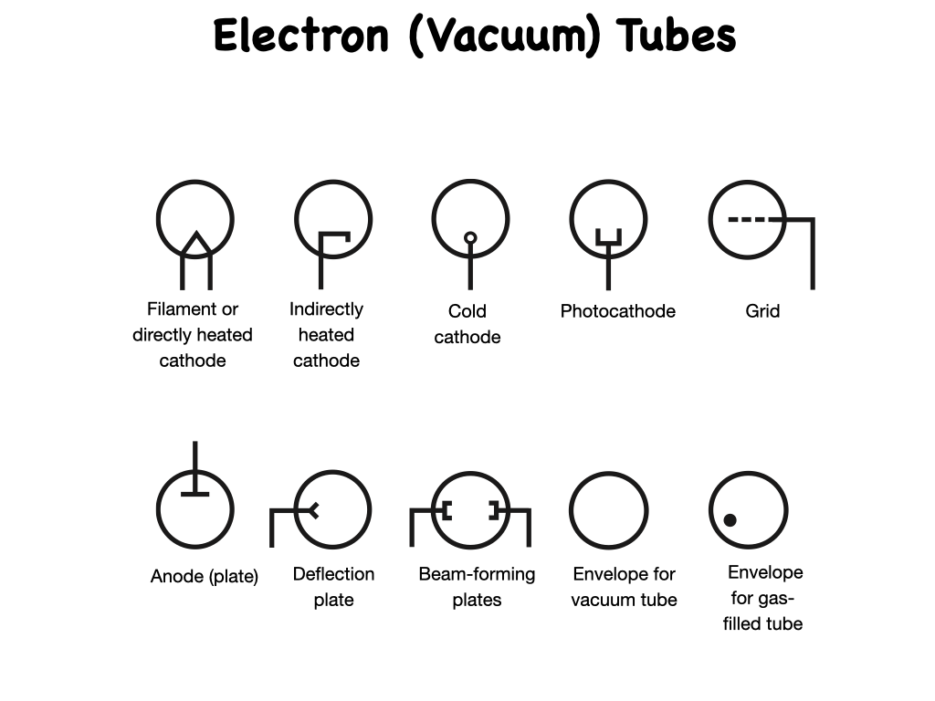
The schematic symbols for the various types of tube elements commonly used in schematic drawings are shown on this slide.
Filament or directly heated cathode.
Indirectly heated cathode.
Cold cathode.
Photocathode.
Grid.
Anode or (plate).
Deflection plate.
Beam-forming plates.
Envelope for the vacuum tube.
Envelope for the gas-filled tube.
All tube elements are surrounded by a circle, which represents the tube envelope. Occasionally, the circle is omitted from some tube symbols in schematic drawings, but that’s not standard practice.

This slide shows the schematic symbol for a diode vacuum tube. This two-element device contains an anode (also called a plate) and a cathode. Just as with the semiconductor diode, the anode is normally positive with respect to the cathode when the device conducts current. The cathode emits electrons that travel through the vacuum to the anode but blocks electrons from flowing to the cathode from the anode. This means that standard current flow will flow from the anode to the cathode but blocks current flow from the cathode to the anode.
A hot-wire filament, something like a miniature low-wattage light bulb, heats the cathode to help drive electrons from it. The filament has been omitted for simplicity, a common practice in all vacuum tube symbology when the filament and cathode are physically separate, an arrangement known as an indirectly heated cathode.

This shows two versions of a triode vacuum tube, which consists of the same elements as the diode previously discussed, with the addition of a dashed line to indicate the grid. The tube at the left has a directly heated cathode, in which the filament and the cathode are the very same physical object! We apply the negative cathode voltage directly to the filament wire; no separate cathode exists. In the tube at the right, we see the symbol for a triode tube with an indirectly heated cathode. In this symbol, the filament is inside the cathode.

Tetrode vacuum tubes have two grids. To represent one of them, we need an additional dashed line, as shown in these drawings. In the tetrode, the upper grid, closer to the anode, is called the screen.
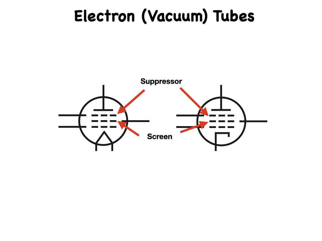
This shows symbols for the so-called pentode tube, which has three grids and a total of five elements. In the pentode, the second grid (going from the bottom up) is the screen, and the third grid (just underneath the plate) is called the suppressor. Again, the left-hand symbol portrays a device with a directly heated cathode, while the right-hand drawing shows a device with an indirectly heated cathode.
In all the vacuum tube symbols shown, electrons normally flow from the bottom up. They come off the cathode, travel through the grid or grids (if any), and end up at the plate. Once in awhile you’ll see a vacuum tube symbol lying on its side. In that sort of situation, you can simply remember that the electrons go from the cathode to the plate under normal operating conditions.

Some vacuum tubes consist of two separate, independent sets of electrodes housed in a single envelope. These components are called dual tubes. If the two sets of electrodes are identical, the entire component is called a dual diode, dual triode, dual tetrode, or dual pentode. This shows the schematic symbol for a dual triode vacuum tube with indirectly heated cathodes.

In some older radio and television receivers, tubes with four or five grids were sometimes used. These tubes had six and seven elements respectively and were called hexodes and heptodes. These esoteric devices were used mainly for mixing, a process in which two RF signals having different frequencies are combined to get new signals at the sum and difference frequencies. The schematic symbol for a hexode is shown on the left; the symbol for a heptode is shown on the right. Some engineers called the heptode tube a pentagrid converter. Both of these symbols show devices with indirectly heated cathodes.
You won’t encounter hexodes and heptodes in modern electronics, but if you like to work with antique radios, you should get familiar with them. But take this warning: You’ll probably have a difficult time finding a replacement component, should one of these relics go “soft” on you!

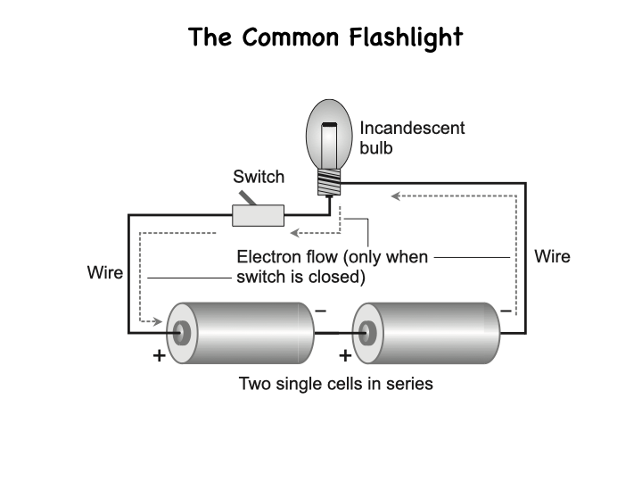
A cell or battery is often used as a power source for electronic circuits. This is the schematic symbol for a single electrochemical cell, such as the sort that you’ll find in a flashlight. A single-cell component such as this usually has an output of approximately 1.5 Volts DC. Electrochemical batteries with higher voltage outputs comprise multiple cells connected in series (negative-to-positive in a chain or string) such as this.
The multicell battery symbol is simply a number of single-cell symbols placed end-to-end without any intervening lines. If a circuit calls for the use of three individual, discrete single-cell batteries in a series connection, you might draw three cell symbols in series with wire conductor symbols between them. Alternatively, if multiple individual cells are set in a “battery holder” designed for direct series connection, you can use a battery symbol to portray the whole bunch.
Standard practice calls for polarity signs to go with the symbols for cells or batteries. Unfortunately, some drafts-people neglect this detail. When you see the schematic, you’ll have to infer the polarity by scrutinizing the rest of the circuit, although it is customary for the longest line to be the positive end.

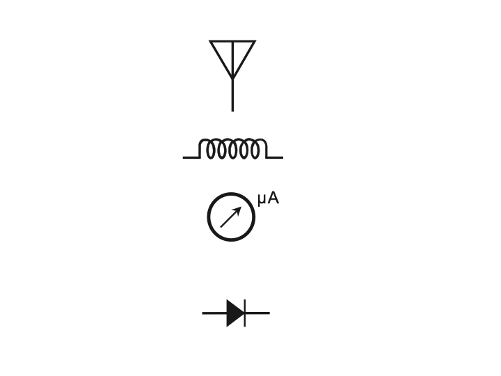
You’ll encounter lots of symbols in electronics other than the common ones shown in this chapter. There are many more schematic symbols in addition to the ones already discussed. There are also symbols for jacks and plugs, piezoelectric crystals, lamps, microphones, meters, antennas, and many other electronic components.
It might, at first thought, seem like a massive chore to memorize all of these symbols, but their usage and correct identification will come to you with practice and with time. The best way to begin the learning process is to read simple schematics and refer to the listing of symbols whenever a symbol crops up that you can’t identify. Within a few hours, you’ll be able to move on to more complex schematics, again looking up the unknown symbols. After a few weekends of practice, you should be thoroughly familiar with most electronic symbols used in schematic representations, so that when you see one in a diagram, you’ll recognize it without having to think about it.
Schematic symbols are the fundamental elements of a communication scheme, like the symbols in mathematical expressions or architectural blueprints. Most schematic symbols in electronics are based on the structure of the components or devices they represent. Schematic symbols often appear in groups, each of which bears some relationship to the others. For example, you’ll encounter many different types of transistors, but they’re all represented in a similar fashion. Minor symbol changes portray variations in internal structure, but all can be easily identified as some type of transistor. The same rule applies to the symbols for diodes, resistors, capacitors, inductors, transformers, meters, lamps, and most other electronic components.
Blog #16 - Block Diagrams (2 of 8 in the Series) Electrical Wiring Diagrams
/
Block Diagrams. A block diagram portrays the general construction of an electronic device, or system. A block diagram can also provide a simplified version of a circuit by separating the main parts, and showing you how they are interconnected.

This is a block diagram of a device that converts alternating current, to direct current. The terminal at the left accepts the AC input. In sequence, going from left to right, the electricity passes through the transformer, the rectifier, and the filter, before arriving at the output as DC. In this case, the lines that connect the blocks do not have arrows because readers will naturally assume that the flow goes from left to right. The input terminal resides at the left-hand end of the diagram, and the output lies on the extreme right. In more complicated block diagrams, the interconnecting lines may include arrows to show which block affects which or to indicate the general direction of signal flow when it might not otherwise be clear.
Another way of using block diagrams starts with a finished schematic diagram. Imagine that the schematic is complicated and that the equipment whose circuit it represents does not work properly. Although schematic diagrams can describe the functioning of an electronic circuit, they are not as clear and basic as a functional block diagram for that purpose.
In the absence of a pre-existing block diagram, a technician would have to start with the schematic, laboriously identify each stage in the system, and then draw the entire system diagram in block form. When finished, the block diagram would reveal how each stage interacts with the others.
Using this method, one or more stages could be identified as a possible trouble area. Then the technician would refer to the original schematic and conduct tests in specific areas, based on his or her knowledge of how each stage works at the component level.

In practice, you’ll often encounter block diagrams. If presented without accompanying schematics, a block diagram describes the basic functional operation of an electronic device or system. The block diagram can prove most useful when you don’t need to know the functions of individual components.
We can describe the operation of a specific type of wireless transmitter, say an amplitude-modulated voice transmitter, such as the type found in Citizens Band radios, by means of a block diagram. This diagram will apply to most other AM voice radio transmitters. Of course, no two transmitters built by different manufacturers are exactly alike, but all of them contain the same basic circuit sections as far as functionality goes. One type of oscillator might work differently from another type, but they all do the same thing: generate a radio-frequency signal! When we need to know or portray, individual differences between circuits that do essentially the same things, then we need schematic diagrams.

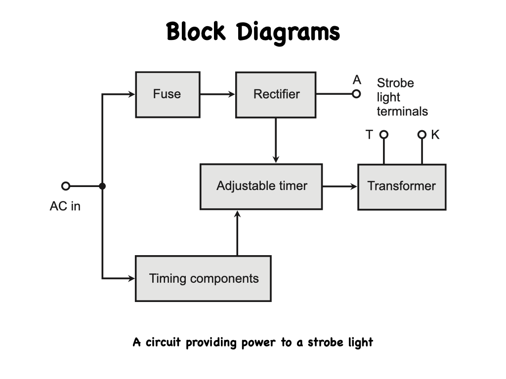
The block diagram here illustrates the various parts of a strobe light circuit. Let’s go through the diagram block by block to under- stand how it works. The input signal enters at the left; it’s utility AC, such as we get from a standard wall outlet. In the United States and some other countries, this AC has a nominal voltage of 117 volts and a frequency of 60 hertz, where “hertz” means “cycles per second.” (In some countries, the voltage is about 234 Volts, and in some countries, you’ll find a frequency of 50 Hz rather than 60 Hz).
The input AC goes to a fuse, and also to a combination of components that provide timing. The top path, where the fuse is located, leads to a diode-type rectifier, and the rectifier output passes directly to one terminal of the three-terminal strobe lamp. The rectifier also outputs to an adjuster that provides a variable flash rate for the lamp. The output from that adjuster goes to a transformer, which supplies the remaining two outputs required to operate the lamp.

This shows a power supply that produces several different voltage outputs. As you go through this diagram from the left, (the input) to the bottom and the right, (the outputs). Note that the circuit is powered with 120 volts AC, quite close to the nominal 117 Volts commonly found at utility outlets in North America.
The input AC goes through a filter and then splits into two paths. Part of the AC goes to the “lower” transformer that provides 16 Volts AC and 3 Volts AC output along with a ground connection. From the filter, the input voltage gets fed to another transformer that derives the voltages to be converted to DC.
One output of the transformer goes to a rectifier that provides 12 volts DC without any voltage regulation. The other transformer output goes to a separate rectifier that provides 18 Volts DC, also unregulated. This transformer output also serves as a diagnostic detector for a power “off” condition. That line is further tapped to join with the output of the voltage regulator, to provide 12 Volts DC, with voltage regulation.
Block diagrams are comparatively easy to draw, comprising squares or rectangles along with interconnecting lines (sometimes with arrows). More sophisticated block diagrams also include triangles to represent circuit blocks built around specialized amplifiers constructed within integrated circuits known as chips.

Here is another block diagram of an AM radio transmitter. The microphone preamplifier stage goes to the input of the audio amplifier stage (note the direction of the arrows). The output of the audio amplifier goes to the matching network, which in turn goes to the RF amplifier section.
The crystal oscillator is also connected to the RF amplifier section, whose output leads into the RF tuning network. Only one connection exists between the audio section of the circuit and the RF section: the one between the matching network and the RF amplifier. This block diagram, with its arrows, tells us not only how the components of the system connect to one another, but also the sequence of events or direction of signal flow.

Block diagrams can describe the functioning of electronic circuits, but in the world of computers, another form of diagramming is sometimes used to portray the functioning of a program. This system is called flowcharting. A flowchart resembles a block diagram, except that the symbology applies to the sections of a computer program, an intangible thing (as opposed to an electronic circuit, a tangible thing). A flowchart provides a graphic representation of the logical paths that a computer will take as it executes a particular program. Flowcharts are often prepared in conjunction with specifications and are modified as the requirements change to fit within the constraints of the computer system.
For complex problems, a formal written specification might be necessary to ensure that everyone involved understands and agrees on what the problem is, and on what the results of the program should be. To illustrate this concept, let’s suppose that a teacher wants to write a computer program that will determine a student’s final grade for a course by calculating an average from grades the student has received over a certain period of time. The teacher will supply the grades to the program as input. Only the average grade is needed as an output. Now, we can make an orderly list of what the program has to do:
1) Input the individual grades.
2) Add the grade values together to find their sum.
3) Divide the sum by the number of grades to find the average grade.
4) Print out the average grade.

We can prepare a flowchart of the program, as shown here. As we can see, the flowchart graphically presents the structure of the program, revealing the relationship between the steps and paths. When the flow of control is complicated by many different paths that result from many decisions, a good flowchart can help the programmer sort things out. The flowchart can serve as a thinking-out tool to understand the problem and to aid in program design. The flowchart symbols have English narrative descriptions rather than programming language statements because we want to describe what happens, not how it happens.
It takes a lot of time to conceive and draw up a formal flowchart and modifying a flowchart to incorporate changes, once a program has been written and its flowchart composed, can prove difficult. Because of these limitations, some programmers will shy away from the use of a flowchart, but for others, it can provide valuable assistance in understanding a program. In order to promote uniformity in flow- charts, standard symbols have been adopted, the most common of which are shown and defined in this slide.
The normal direction of processes in a flowchart runs from…top to bottom and from left to right, the same way as people read books in most of the world. Arrowheads on flow lines indicate direction. The arrows can be omitted if but only if, the direction of flow is obvious without them.

This is a flowchart for a program that duplicates punched cards and at the same time prints the data on each card. Keep in mind that this particular “beast” is of historical interest only! (Were you born long enough ago to remember punch cards for inputting programs into computers? I recall using them, all the way back in the 1960s when I attended university. I guess that little fact kinda dates me, doesn’t it?
Tracing the flow of the program. The program begins at the “Start” oval at the top and proceeds in the direction of the arrows. In the first box below “Start,” the program reads a card. Then the program punches the card’s contents (data) as holes in a blank piece of heavy paper and sends the data to a printer.
The program then goes back to the top and reads the next card. The circles marked, “A", represent inflow and outflow points. In this case, they’re superfluous, but in complicated flowcharts, they can be useful when it would create a mess to include all the applicable dashed lines. The program repeats itself as long as it has cards to read and punch.

In a sophisticated flowchart, we might see several different symbols. Oval boxes show, start, or stop points; Arithmetic operations go in rectangular boxes; Input and output instructions go in upside-down trapezoids. If we want to show a program that someone wrote earlier within the context of a larger flowchart, we don’t necessarily have to draw the flowchart for the inside program. Rather, we might represent the entire program as a flattened hexagon.
If a box indicates a decision, we use a diamond shape; A five-sided box portrays a part of the program that changes itself.
A small circle identifies a processing junction point. Such a point in the program can go to several places.
A small five-sided box, which has the shape of the home plate on a baseball field, shows where one page of a flowchart connects to the next if the entire flowchart has more than one page. The intermediate junction and off-page connection points are labeled with numbers and letters to let readers know that all like symbols, with the same character inside, are meant to be connected together.
Arrows indicate the direction of the flow.

Looking at the flowchart for duplicating punched cards, suppose that you want to change the card-punching program so that the computer skips blank cards and duplicates only those cards with some holes in them.
Because the computer must make a decision about each card, you’ll need to include a decision block in the flow- chart.
Except for the decision block, this shows the same process as the previous process path does. The program begins in the “Start” oval at the top and then goes to the block marked “Reed a card.” From there, the program moves on to the decision block labeled “Card blank?” If the answer is “Yes,” the program proceeds to the connection circle marked, “A” and back to the top to read the next card. If the answer is “No” (the card has holes in it), the program instructs the hardware (the physical components of the computer) to punch a duplicate card and print its contents. Then the program goes to another circle marked, “A” and back to the starting point.
These are simple flowcharts, showing a process that uses only input and output devices and that does no calculations. Most programs and flowcharts involve more complicated processes.

Closely related to the block diagram is the "operating diagram”. It is also closely related to the one-line diagram, but without the protection and control data that's on one-line diagrams. Operating diagrams are used by the operating staff to operate the system whether it's electrical, water, or fluid flow, or any other system that needs to be understood when operating it. In this series of blogs, we will be concentrating on the electrical systems.
Operating diagrams are similar to block diagrams in that the system is made up of blocks and pictorial elements that represent items such as breakers, disconnect switches, transformers, etc, to which power runs along a single connecting line. The flow of power is represented by single lines connecting these elements.

Operating diagrams are designed primarily to assist in the operation and maintenance of a power system. In addition to diagrams of electrical systems, operators and maintenance personnel must also refer to diagrams of compressed air, steam and hydraulic systems. A large portion of the information in any diagram is conveyed by symbols. In order that each diagram will convey the same information to everyone reading it, symbols have for the most part been standardized. The Standard for electrical operating diagrams is quite rigid and there is virtually no duplication of symbols in use.

The field of microcomputers uses many different types of diagrams that deal mostly with software (the operating systems and programs) rather than hardware (the physical components). From a purely electronic standpoint, functional diagrams abound and are usually more numerous than schematic diagrams in the computer world. From an understanding standpoint, block diagrams can serve to display machine functions in general, but hardware maintenance and repair procedures require well-defined schematic drawings. Computers take advantage of the latest state-of-the-art developments in electronic components and are relatively simple from this standpoint, especially when you consider all they can do. However, from a pure electronics standpoint and as far as schematic diagrams are concerned, computers are highly complex; it would take many pages of schematics to represent even the most rudimentary computer.
Block diagramming can help you understand the general functioning of electronic circuits. Block diagrams are easy to draw, usually requiring only a marking instrument, some paper, and a straightedge (or a vector graphics computer program and a little bit of training on it). Schematic diagrams, in contrast, need more tools and can in some cases, take many hours to render in a form that people can easily read and interpret.
Blog #15 - Electrical Wiring Diagrams (1 of 8)
/
Electrical Engineers and technicians are often called on to install and maintain hundreds of different types of devices. As these devices have grown in variety and complexity, a system of symbols, and conventions evolved to describe the circuits in a shorthand method of documentation. This allows engineers, designers, and technicians, to understand how the circuits that make up a device work, and how its components connect with each other. Although the schematic diagram is the most common document for this function, there are also block diagrams, wiring diagrams, and other diagrams. Each of these documents has a unique function in describing the circuit to aid in under- standing and troubleshooting.
Technicians encounter some differences between North American company schematics, and those produced in European, or Asian countries. In this series you’ll study mostly the schematics you’ll see from North American companies, but once you’re accustomed to reading these, you’ll recognize common characteristics in all other schematics.

Schematic diagrams document the connection points and construction methods of electrical and electronic circuits. This shows a simple schematic diagram of a power supply; on it, you can see some of the conventions used.
Schematic diagrams are often read from left to right, like a book, with inputs on the left and outputs on the right. This isn’t a universal practice, but it’s a good way to begin your analysis of the schematic. Schematic diagrams show the connections of the components in a clear, easily readable format, but they don’t show how the components are physically arranged. In this schematic, you’ll see a plug on the left side; this means the supply (or any device with this symbol) is powered by an AC source, which isn’t shown.
The fuse is in series with the power transformer to prevent damage from overloads, and the switch controls the on and off status of the supply.
Note that neither of the transformer primary wires are grounded.

This shows the symbols for such basic components as wires and connections, switches, power sources, transformers, fuses, and ground connections. In addition to these standard symbols, you’ll sometimes run across symbols that are variations of these, or ones that are specific to certain companies, especially in older schematic diagrams. I will deal with these more specifically later.

In your work, you may encounter a type of schematic called a ladder diagram, as shown here. The general layout of the wires and components resembles a ladder, with vertical rails and horizontal rungs. The input voltage is usually on the left vertical rail; the ground or neutral is on the right vertical rail, and the components are found on the horizontal rungs that connect the two rails. Newer schematics such as this one usually incorporate the symbols used in software that generates the schematics.
This type of schematic is used in control applications for equipment that controls a sequence of operations. For example, a washing machine goes through predefined steps each time a cycle is started, and there are a number of options available at the beginning of and during the wash cycle. Depending on the settings of switches, different actions are possible. In industrial applications, a programmable logic controller (PLC) is often used to control the steps and options with a program installed in the controller. You’ll find PLCs in a variety of industrial applications such as robotic welders, assembly lines, and packaging operations.

Here are some typical symbols used in programmable logic controller diagrams. You’ll see that the symbols on the rungs are switches, motors, contacts, timers, and other high-level devices, and not individual components such as capacitors, diodes, amplifiers, or transistors. Ladder diagrams are usually best understood by reading them from top to bottom and left to right, since the cycle of operations is often performed in that sequence. The power connections are generally at the top of the ladder, and the left rail is the hot side, while the right rail is the neutral, or common. Options in the sequence are determined by the condition of sensors or control settings. Relays, switches, and other controls are always shown in the unenergized state, meaning that the equipment hasn’t been activated to perform the operation.

You’ll encounter three types of diagrams in electricity and electronics:
1) The block diagram,
2) The schematic diagram, and
3) The Wiring Diagram or Layout diagram. Each type of diagram serves its own special purpose.

A block diagram gives you an overview of how the discrete circuits within a device or system interact. Each circuit is represented with a “block” (a rectangle or other shape, depending on the application). Interconnecting lines, sometimes with arrows on one or both ends, reveal the relationships between the circuits.

A schematic diagram (often simply called a schematic) includes every component that a circuit contains, with each component having its own special symbol. This blog is devoted mostly to schematics.
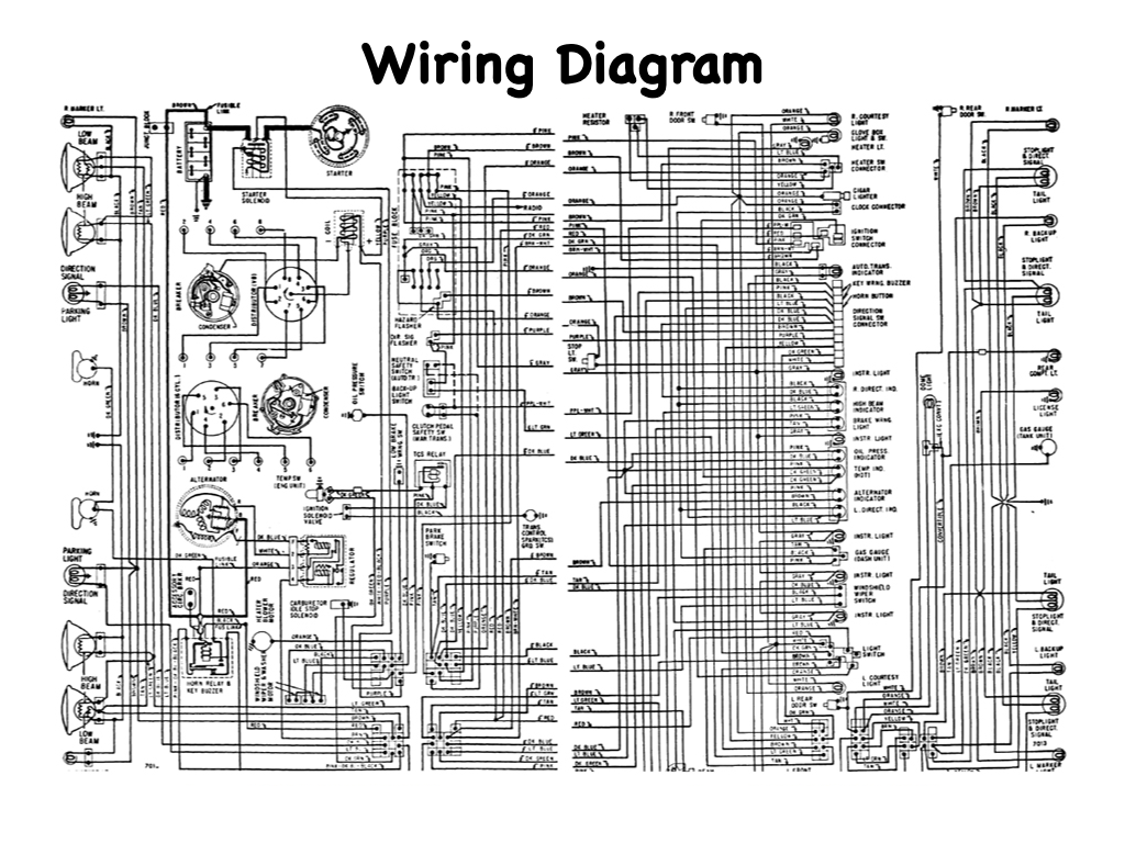
A pictorial diagram, sometimes called a wiring or layout diagram, shows the actual physical arrangement of the circuit elements on a circuit board or chassis, so that you can quickly find and identify components to test or replace.

When you troubleshoot an unfamiliar electronic circuit, you’ll usually start with the block diagram to find where the trouble originates. Then you’ll refer to the schematic diagram (or part of it) to find the faulty component in relation to other components in the circuit.
A Layout or wiring diagram can then tell you where the faulty component physically resides so that you can test it, and if necessary, replace it.

Block diagrams work well in conjunction with schematics to aid circuit comprehension and to streamline troubleshooting procedures. Each block represents all of the schematic symbols related to that part of the circuit. In addition, each block has a label that describes or names the circuit it represents. However, the block does nothing to explain the actual makeup of the circuit it represents. The blocks play a functional role only; they describe the circuit’s purpose without depicting its actual components. Once you’ve gained a basic under- standing of the circuit functions by looking at the block diagram, you can consult the schematic for more details.
To understand how you might use block diagrams, consider these two examples.
First, suppose that you want to design an electronic device to perform a specific task. You can simplify matters by beginning with a block diagram that shows all of the circuits needed to complete the project. From that point, you can transform each block into a schematic diagram. Eventually, you’ll end up with a complete schematic that replaces all of the blocks.
Alternatively, you can go at the task the other way around. Imagine that you have a complicated schematic, and you want to use it to troubleshoot a device. Because the schematic shows every single component, you might find it difficult to determine which part of the device has the problem. A block diagram can provide a clear understanding of how each part operates in conjunction with the others. Once you’ve found the troublesome area with the help of the block diagram, you can return to the schematic for more details.

A schematic diagram acts in effect, as a map of an electronic circuit, showing all of the individual components and how they interconnect with one another. According to one popular dictionary, the term schematic means, “of, or relating to, a scheme diagrammatically.” Therefore, you can call any drawing that depicts a scheme—electronic, electrical, physiological, or whatever, a schematic diagram.
One of the most common schematic diagrams finds a place in almost every car or truck in the United States. Like this schematic diagram of an electronic circuit, that shows all the components relevant to the scheme it addresses. An electronic schematic shows all of the relevant components, and it allows a technician to extrapolate the components and interconnections when testing, troubleshooting, and repairing a small circuit, a large device, or a gigantic system.
A schematic drawing must indicate not only all components necessary to make a specific scheme but also how these components interrelate with one another.
An electronic schematic drawing uses a plain straight line, to indicate a standard conductor, other types of lines represent cables, logical pathways, shielding components, and wireless links. In all cases, when you draw the interconnecting lines, you draw them in order to indicate relationships between the connected components.

A schematic diagram reveals the scheme of a system by means of symbology. On a map, the lines that indicate roadways constitute symbols. But of course, a single black or in this case white line that portrays Route 395 in no way resembles the actual appearance of this highway as we drive on it!. We need to know only the fact that the line symbolizes Route 395. We can make up the other details in our minds. If people always had to see pictorial drawings of highways on paper road maps, those maps would have to be thousands of times larger than those folded-up things we keep in our vehicle glove compartments, and they would be impossible for anybody to read.

On any decent road map, you’ll find a key, or (Legend), to the symbols used. The key shows each symbol and explains in plain language, what each one means. If a small airplane drawn on the map indicates an airport and you know this fact, then each time you see the airplane symbol, you’ll know that an airport exists at that particular site, as shown on this map. Symbology depicts a physical object, (such as an airport, outside a large city) in the form of another physical object (such as an airplane image on a piece of paper). A good road map contains many different symbols. Each symbol is human engineered to appear logical to the human mind. For instance, when you see a miniature airplane on a road map, you’ll reasonably suppose that this area has something to do with airplanes, so a detailed explanation should not be necessary. If, on the other hand, the map maker used a beer bottle to represent an airport, anyone who failed to read the key would probably think of a saloon, or liquor store, not an airport! Because a map needs many different symbols, a good map maker will always take pains to make sure that the symbols make logical sense.

Pure logic will take us only up to a certain point in devising schemes to represent complicated things, especially when we get into the realm of electronic circuits and systems. For example, a circle forms the basis for:
1) a transistor symbol,
2) a light-emitting-diode symbol, and
3) a vacuum tube symbol.
Additional symbols inside the circle tell us which type of component it actually represents. A transistor is an active device, capable of producing an output signal of higher amplitude than the input signal. We can say the same thing about a vacuum tube, but not about an LED.
A circle with electrode symbols inside has been used for many years to represent a vacuum tube. Transistors were developed as active devices to take the places of vacuum tubes, so the schematic symbol for the transistor also started with a circle. Electrode symbols were inserted into this circle as before, but a transistor’s elements differ from a tube’s elements, so the transistor symbol has different markings inside the circle than the tube symbol does. The logic revolves around the circle symbol. Transistors accomplish many of the same functions in electronic circuits as vacuum tubes do (or did), so symbolically they are somewhat similar.
Inconsistencies arise in schematic symbology, and that’s a bugaboo that makes electronics-related diagrams more sophisticated than road maps. A circle can make up a part of an electrical symbol for a device that doesn’t resemble a tube or transistor at all. An LED, for example, can be portrayed as a circle with a diode symbol inside and a couple of arrows outside. An LED is not a transistor or tube, and the electrode symbol at the center clearly reveals this difference. You’ll learn more about specific schematic symbols later.
To further explore how schematic diagrams are used, let’s consider a single component, a PNP transistor. This device has three electrode elements, and although many different varieties of PNP transistors exist, we draw all their symbols in exactly the same way. We might find a PNP transistor in any one of thousands of different circuits! A good schematic will tell us how the transistor fits into the circuit, what other components work in conjunction with it, and which other circuit elements depend on it for proper operation. A transistor can act as:
1) a switch,
2) an amplifier,
3) an oscillator, or
4) an impedance-matching device. A single, specific transistor can serve any one of these purposes. Therefore, if a transistor functions in one circuit
5) as an amplifier, you can’t say that the component will work as an amplifier only, and nothing else. You could pull this particular transistor out of the amplifier circuit and put it into another device to serve as the “heart” of an oscillator.
By knowing the type of component alone, you can’t tell what role it plays in a circuit until you have a good schematic diagram showing all the components in the circuit, and how they all interconnect. Rarely can you get all this information in easy-to-read form by examining the physical hardware. You need a road map…a schematic diagram, to show you all the connections that the engineers and technicians made when they designed and built the circuit.

An electronic circuit is similar to a road map in that it may have many electrical highways and byways. Occasionally, some of these routes break down, making it necessary to seek out the problem and correct it. Even if you can visualize the circuit in your head as it appears in physical existence, you’ll find it impossible to keep in your “mind’s eye” all the different routes that exist, one or more of which could prove defective. When I speak here of visualizing the circuit, I don’t mean the schematic equivalent of the circuit, but the actual components and interconnections, known as the hard wiring.
A schematic diagram gives you an overall picture of a circuit and shows you how the various routes and components interact with other routes and components. When you can see how the overall circuit depends on each individual circuit leg and component, you can diagnose and repair the problem. Without such a view, you’ll have to “shoot in the dark” if you want to get the circuit working again, and you’ll just as likely introduce new trouble as get rid of the original problem!

Look at this schematic…If you’ve had little or no experience with these types of diagrams, you might wonder how you’ll ever manage to interpret it and follow the flow of electrical currents through the circuit that it represents. By the time I am finished with this series of blogs, and, assuming that you already know some basic electricity and electronics principles, you’ll wonder how you ever could have let a diagram like this intimidate you.
Blog #14 - The House Main Electrical Panel
/

Connecting homes to the electrical grid is the final stage of the electrical grid. After the substations have stepped down the voltage to acceptable distribution levels, this stage may be accomplished. Wires lead off from the neighborhood's power lines and connect to individual buildings, (homes, apartments, and businesses,). But first must go through the electric meter to measure how much electricity the customer uses. The electricity then passes through a Service Panel, which houses the electrical safety devices (circuit breakers or fuses). This service panel has all of the wires that run to the different electrical outlets around the house.
Every home is connected to the electrical grid through some sort of fuse box or Circuit Breaker Panel.
The overhead power connection from the utility lines to the service entrance is referred to as the service drop. It has three wires. One neutral line, and two hotlines. The hotlines maintain a certain potential (like 120 Volts) compared to the neutral line. There are two types of overhead service drops, a mast service drop, and an underground service connection.
The service connection enters the panel via the main disconnect breaker, which is utilized to isolate the complete home by stopping all electrical power flow. This is positioned between the service meter and the rest of the electrical panel. The main disconnect is a circuit breaker housed in the electrical panel. In order for this to work, the circuit breakers must be in series with the two hotlines of the conductors, because it must cut power to all circuits. It is rated to be able to interrupt the total household load.

A Circuit Breaker is an electrical switch, that cuts off electrical flow, in the event of a possible short circuit or overload. This device is essential in a modern world that runs on electricity. Without a circuit breaker, you could find yourself dealing with household fires on a regular basis. While you can easily call a professional electrician, you can also learn how to wire a circuit breaker yourself, with relative ease.

Because most power panels today are breaker panels, I'm gonna deal exclusively with breaker panels. If you are to do any work inside the main breaker panel the first thing you must do is switch off the main power switch or breaker. This is usually, but not always, at the top of the breaker panel. It should be the largest switch breaker in the panel, and will also be rated the highest amp rating in the panel.
Take the cover of the breaker box off. It is usually held in place by 4 to 6 large screws located on the perimeter of the cover. You may accidentally trip off some of the lower voltage breakers when doing this, however, this is not a problem, as long as you remember to switch them back on, when you're finished.


This is a sketch of what you will find, inside a standard power panel. At the top, in most instances, is the main breaker. The two hot wires from the utility will be connected here. The neutral from the utility is connected to a neutral bar, which can be located on either side and, sometimes, on both sides of the panel. The ground bar, which receives all of the ground wires, is located on either side of the power panel and can be identified by its connection to the ground rod. All of the circuit feeder breakers are located in the middle of the panel. Cables from the various outlets in the house enter the panel through knockouts that are located on the perimeter of the panel. The hot wires are connected to the breakers in the middle of the panel, while the neutrals are connected to the neutral bar, and the ground wires are connected to the grounding bar.

Depending on the size, and gauge of the wire, a knockout bushing must be used when stringing the wire through the panel side. This bushing, for number 14 three wire, and number 14 two wire, is usually half an inch, but the knockouts and bushings could be as big as 3/4 of an inch.
The bushing not only protects the wire from the sharp edges of the panel box, but it also locks the cable and wires in place.

This picture shows the installation of a single pole breaker, protecting a 120 volt, number 12 two Cable, a double pole breaker, protecting a 240 volt, number 10 two Cable, and a double pole breaker, protecting a 120/240 volt, number 10 three Cable. With the breaker switch in the “OFF” position, install it on the main bus. Many breakers have a hooked outer edge, slide it into the hot bus bar until it engages, then firmly push the other end down, over the protrusion on the breaker until you hear a “click”.
This diagram also illustrates some of the most common circuits found in a typical breaker service panel box. The breakers are installed in a panel so that contact is made with one or both of the hot bus bars running down the middle of the box. The hot wire for a branch circuit is connected to the breaker by a set screw on the base. The neutral and ground wires for the circuit are connected to a bar along the side of the service panel box. The neutral and grounding bars in the panel may be separate, or, in the case of older service panels, the same bar may be used for both purposes.

This wiring diagram illustrates installing a 15 amp circuit breaker, for a 120 volt branch circuit. The 14 two cable for this circuit, includes 2 conductors and 1 ground wire. A 15 amp circuit is usually used for wall receptacle outlets, and light fixtures.
This diagram illustrates, the arrangement for a 20 amp, 120 volt, double receptacle circuit, with a shared neutral wire. This arrangement is typically used in a kitchen, or over a workbench, where two separate appliance circuits are needed in close proximity to each other. Notice that the breaker is a “Ganged” breaker, which means that it switches, or trips, both circuits at the same time. This arrangement is absolutely protected, but can supply a total of 40 Amps, from a 20 Amp breaker, provided that the load is evenly split between the two receptacles.


This circuit breaker wiring diagram illustrates installing a 20 amp circuit breaker, for a 240 volt circuit. The 12 two gauge cable for this circuit, includes 2 conductors and 1 ground. The white wire is used as a hot in this circuit, and it is usually marked with black tape on both ends, to identify it as such. A neutral wire is not used in this circuit. A dedicated 20 amp circuit, like this, is used for a heavy household appliance, like large window air conditioners.
This is an outdated circuit, that may still be in use. This wiring is for a 30 amp circuit breaker, serving a 30 amp, 240 volt receptacle. The 10 three cable for this circuit, has 3 conductors, and no ground. Although the newer installations will have a bare copper ground. A 30 amp circuit like this may be found in older installations for clothes dryers and maybe a kitchen cooking range as well.

This is a diagram for a new 30 amp circuit breaker, to serve a 30 amp dryer outlet. This is an upgrade of the outdated 30 amp circuit in the previous diagram. This breaker is connected to a 30 amp receptacle, with a 10 three cable, including a ground wire.
This diagram illustrates the wiring for a circuit breaker, with a built-in ground fault, circuit interrupter, or GFCI. This 20 amp, 120 volt breaker, is a form of GFCI, that can be installed at the circuit source. This kind of circuit is used for dishwashers, whirlpool spas, and other locations, where water contact is likely.


Blog #13 - House Wiring Diagrams
/
A wiring diagram is a pictorial representation of an electric circuit, where the elements of the connections, between devices, and the power source are shown in the conventional methods as simplified shapes. A house wiring diagram is thus, a wiring diagram of a house.
This diagram can be a wiring diagram, for any electric circuit in your home, which is drawn mostly so that it can easily guide the electrician (or yourself) when needed. The diagram consists of connections between elements of the circuit, and their relations, to and from the power source.
It takes into account, the dimensions of the room, and the input and output points, keeping in mind the access to those points.
House wiring diagrams are the visual representation, or design of the entire electrical wiring system, or circuitry of a house (or a room) that helps in creating the system to distribute energy that can be used to power the various equipment and appliances around the house. It will aid in the proper installation and operation of the different elements, included in the design, such as electrical outlets, the meter base, switches and breakers and more.
In this blog, we will talk about the various aspects of a basic house wiring diagram. We will understand what it is, why we need it, what benefits we can gain from it as well as the principles and symbols involved in the whole process. Finally, we will look at some examples, and see how we can draw a house wiring diagram.
The above house wiring drawing is what I would call, the minimum requirement. It shows switches, and electrical outlets, (lights and receptacles). It indicates where and how the lights are controlled, and from which switches, but leaves the details of how they are connected, to the electrical contractor. As you will see in the following information, details can be added, for example where the feed wires go, and the circuits that are connected to the various feeds.

All of the drawings in this blog were constructed using the software EDraw Max. EDraw Max.anrdoezrs.net/click-100680115-14099230 is the best diagram solution to help you design, create, improve, and achieve your goals. It’s an all-in-one graphics software that makes it simple to create floor plans and electrical diagrams.
Find on the E-Draw Max link

There can be no question as to the importance of a House Wiring Diagram. But still, we must address the need for using one. It is a vital part of wiring a house. The reasons are as follows:
Financial: An electrician can only estimate the amount of wiring needed to set up the electrical system. The house wiring diagram, on the other hand, can give the exact value. Say your electrician does not use a house wiring diagram, this can lead to severe inefficiencies. There can be two possible scenarios:
Without an exact amount, your electrician may end up using more wiring, which can lead to wastage and excess installation, which leads to cost overruns.
The opposite can also happen, less wiring would mean spending time buying the remaining wiring which leads to delays and ineffective costing.
Timescale: Not only finance, but also the timeframe of the work gets affected. Without an adequate amount of wiring, you will need to buy more or wait for the new installation to be delivered. It can hamper the timeframe and coordination of the work, especially on big projects, like that of an apartment building, or a condominium.
Safety: Whenever working with electrical systems, we are all taught to look out for safety. Injuries can happen anywhere, anytime, and due to many reasons. A useful house wiring diagram can show where the points of danger lie in the whole network. It can help to avoid hazards, open hot wires, and many other such scenarios. An injury would mean time delays as well as an expensive hospital bill. A House Wiring Diagram thus also serves as a tool for avoiding mishaps.

Wiring diagrams use an array of special symbols that represent various circuit elements, like switches, bulbs, electric outlets, breakers, smoke detectors, and many more. This table lists the most common symbols along with their names. Other than these symbols, there are some lighting, electrical and telecom, and wall, shell or structure symbols that are involved in a house wiring diagram. In fact, there is a plethora of symbols, that are currently in use and new ones constantly being introduced to the mix. However, they are usually self-explanatory, especially when a lot of them, will come with side text, that further explains the symbol.

To start with, let's look at the details that can be added to the bedroom wiring, starting with bedroom number one.
Locating the power panel in the garage, the first feed wire will be connected to the two-ganged switch box in this bedroom next to the door. One switch will control the ceiling light, and the Second switch will control the tops of the duplex plugs in the bedroom. Looking at the next two bedrooms, a second Circuit will bring power to these rooms, starting at the closest duplex plug of bedroom three.
The power will then extend to the two adjoining duplex plugs, as well as bringing power to the bedroom light switch, which controls the overhead light in this bedroom. Because we want to continue the power feed to the light independent of the light switch, we will connect the switch to the bedroom overhead light with a #14-3 Cable wire. This will allow us to drop the feed to the fourth duplex plug in the bedroom.
We will carry on this circuit into bedroom number two, to the closest duplex plug, and then to the overhead light in the bedroom which is switched from a position next to the entrance door. The circuit is also extended to the other two duplex plugs in the bedroom.
The light in the closet is being fed from the overhead light in the bedroom. Because the closet light is a pull-chain, it does not require a wall switch, moreover, we can finally feed the last duplex plug in the bedroom from the closet light as shown.
We are now going to look at the bathroom wiring in more detail…A third feeder wire is brought in from the power panel in the garage, and connected to the switch box in the main bathroom.
We want to add exhaust fans in both bathrooms. For the small bathroom, it will be in the light fixture and will come on with the light. But in the main bathroom, we want a separate fan controlled independently from a second switch.
We will use a #14 three cable from the switch to the main bathroom light in order to carry on a power feed to the smaller bathroom.
Power is fed from the two gang switch box to the duplex outlet receptacles in the bathrooms. The duplex plug in the main bathroom is a GFCI, (Ground Fault Circuit Interruptor) receptacle, which is a code requirement. The receptacle in the smaller bathroom is not required to be a GFCI if it is fed from the load side of the main bathroom receptacle as shown.

Let’s unscramble the confusion surrounding the kitchen lights, which are two lights, each controlled by a set of three-way switches. We are going to feed these light circuits at the three gang switch receptacle next to the garage door, picking up one of the garage duplex receptacles along the way.
Let's look at how a three-way switch schematically controls a light. Switch #2 is being fed with power, from a hot wire connected to its common terminal. Switch number 1’s common terminal is connected to the hot terminal of the light, Neutral is connected to the neutral terminal of the light and the carrier terminals of the switches are connected in parallel.

A three-way switch is a single pole, double throw type of switch which looks like this, schematically. I am going to color code the wires red that are electrically hot, or at 120 volts, for various positions of the switches. With the switches in this position, the red wires` are the wires that are hot. As you can see, the light is off.
Toggling switch #1, carries 120 volts all the way to the light. The light is now on.


When switch #2 is Toggled, the hot circuit to the light is interrupted, and the light once again is off.
Toggling switch #1, again completes the circuit to the light. The light is once again on.


I have maintained the same connections as the schematic drawing, but this time I am placing the components, the two three-way switches and the light, in separate electrical boxes, as in real life. The electrical box boundaries are indicated by the blue dotted rectangles. The feed wire is the #14-2, NMD cable, entering switch box #2 on the right. A #14-3, NMD Cable, is connected between switch box #1 and switch box #2. The white wire of this cable is not connected to either of the switches, but jumpers the neutral from the feed wire, through to the light. The red and black wires of this #14-3 cable, are connected to the carrier terminals of each switch. It does not matter, which carrier terminal is connected to which wire. Finally, a #14-2 cable carries the neutral and the switched hot wire, from switch box #2 to the light. Replacing the actual switches, the set up will look more realistic.

Now that we have the three-way lights figured out. Let's complete this one circuit by picking up the last outlet in the dining room area, and the refrigerator circuit by bringing the feed from that circuit over to the innermost receptacle in the garage, and then continuing on to feed the switch, which ultimately lights the laundry room area.
The last remaining outlet in the dining room area, will be on a separate feed, for no other reason other than we have lots of available circuits.
The next two feeder circuits will be brought out on #12-2 wire that is going to be fused with a 20 amp AFCI breaker, or an Arc Fault Circuit Interrupter breaker.
The dishwasher is going to be fed with a #14-2 cable, and a separate, 15 amp standard breaker. Next, we have to connect the washer and dryer. The dryer load will require a #10-3 feeder cable, and a 30 Amp, double pole breaker. The washer will only require a #14-2 feeder cable, and a 15 Amp single pole breaker.
The Range load will require a #8-3 feeder cable, and a 40 Amp double pole breaker.
Finally, the last outlet plug in the garage will be fed from a separate breaker rated at 15 amp.

All of these drawings were constructed using the software EDraw Max. EDraw Max is the best diagram solution to help you design, create, improve, and achieve your goals. It’s an all-in-one graphics software that makes it simple to create professional-looking graphics. For this blog, I used a combination of floor plans and Electrical diagrams.
Blog #12 -Household Electrical Wiring - Boxes & Connections
/
This blog is a continuation of low-voltage electrical wiring found in residential homes. Most of it applies to any installation that uses a 120/240 AC volt supply. We will begin this blog by going over the different types of electrical boxes.

Electrical boxes are critical components of your home's electrical system. But for many do it yourselfer's, the wide variety of boxes is bewildering. There are plastic and metal boxes; "new work" and "old work" boxes; round, square, and octagonal boxes; and boxes with load ratings for ceiling fans and heavy light fixtures.
All of the most commonly used boxes for home wiring projects, are available at home centers and large hardware stores, and it's important to know the differences in order to buy the correct boxes. There are a number of options to consider: material, shape, size etc.

Most electrical boxes are either metal or plastic. Metal boxes are generally made of steel, while plastic boxes are either PVC or fiberglass. Weatherproof metal boxes for outdoor use are generally made of aluminum.
If you are using metal conduit to run wiring to the electrical box, then a metal box is required, both to anchor the conduit, and because the conduit and metal box system itself may be used to ground the system. If you are using non-metallic cable, such as Type NM (non-metallic sheathed cable), then you can use either plastic boxes or metal boxes, as long as the cable is secured to the box with an appropriate cable clamp.
Modern wiring systems with NM cable usually include a ground wire inside the cable, so the box is not part of the grounding system (however, metal boxes, must be connected to the system ground, usually with a short length of wire called a pigtail).

Like standard rectangular boxes, some are used to hold household switches and electrical outlets, as well some are oversized so that two, three, or four devices can be mounted side-by-side. Like other boxes, these come in a variety of "new work" and "old work" designs, some with built-in cable clamps.
The same effect can be created by using standard rectangular boxes with a "gangable" design that allows the sides to be removed so the boxes can be joined together to form larger boxes.

Round pan or "pancake" boxes typically are only 1/2 inch or 3/4 inch deep. They are used most commonly for ceiling or wall mounted light fixtures that weigh no more than 50 pounds. Some types of specially rated metal pan boxes may be used for mounting ceiling fans, but not all pan boxes may be used for this purpose.
It's important that the fixture wires can be properly connected and fitted within the round pan box. These are shallow electrical boxes with only enough space for fitting two or three electrical connections. If there are more wire connections to be made, you will probably need a full-sized octagon or round electrical box with more volume. The number of wires in the box should never exceed its safe fill capacity.

Square boxes come in standard depths of 1 & 1/4 to 2 & 1/8 inches, but their square corners give them additional interior space, providing maximum volume for multiple conductors and connectors. For this reason, 4-inch square boxes often are used to run multiple conductors in two or more directions. They are also commonly used as junction boxes, and can also be installed in ceilings or walls for supporting lighting fixtures or for housing switches or receptacles when matched with the proper cover plates.
This is also known as a junction box. It is not a special type of box, but rather a term used to describe any standard electrical box used to enclose wire splices. The standard box used for junctions is a 4-inch square box, which offers plenty of space for making wire connections with multiple wires or cables, but other types of boxes can be also used for this application.
Junction boxes must be installed where they are always accessible Never install a junction box in a concealed wall, or ceiling space, where the box cannot be accessed in the future. Junction boxes also must be covered with solid covers with no holes.

Electrical box covers come in a wide variety of sizes and shapes, to match different types of boxes. A cover is used to enclose the front of the box and is required by code; it is unsafe, and usually illegal, to leave an electrical box uncovered.
Solid, or "blank," covers have no holes and typically are used with junction boxes, or for enclosing unused boxes. Covers for 4-inch square boxes may have special cutouts or knockouts to accommodate switches or receptacles (outlets). These typically include a raised center area that extends the box so the opening for the switch or outlet will be flush with the exposed surface of the drywall or other wall or ceiling finish.

Weatherproof, outdoor boxes, are sealed enclosures, designed for mounting to the surface of exterior walls, roof overhangs, decks, and other structures. They are used for installing outdoor receptacles (outlets) and light fixtures. Outdoor boxes must have an outdoor cover, or fixture rated for damp or wet locations, depending on the application.
Plastic outdoor boxes are usually made from high-impact PVC, while metal outdoor boxes are typically made from aluminum rather than steel.

Box extenders, or extension rings, come in a variety of sizes and shapes to match standard electrical boxes. They are shaped like boxes but have no back. They are designed to be installed onto the front of standard electrical boxes to increase the box capacity or to bring the box flush with the drywall or other surface material.

The National Electrical Code, (NEC), dictates that no wiring splices are allowed outside of an approved enclosure. Any standard outlet, switch box or light fixture box, can serve as an approved enclosure, but where a wiring splice, needs to occur in other locations along the circuit, the approved enclosure is usually a junction box. A junction box is simply a standard electrical box, that is mounted securely to house framing or another structure, containing the connection or (splice) of two or more circuit cables. The cables are secured to the box with cable clamps or conduit connectors if the circuit includes conduit, and the box must have a removable cover, to create a complete enclosure. Junction box covers must remain accessible, they cannot be covered with drywall or other surface material.
A junction box is most often used where an electrical circuit branches off in two or more directions from a location where an outlet or fixture is not practical. It is also a common solution when an electrical circuit is being extended.
Make sure to buy a junction box appropriate for your installation. Outdoor locations, for example, require a weatherproof junction box, with gaskets to prevent moisture intrusion. And, make sure the junction box is large enough for the number of wiring connections you will be making. For example, the smallest 2 by 4 by 1 & 1/2-inch deep box can comfortably splice only two cables (four or five conducting wires), while the largest 4 by 4 by 2 1/8-inch-deep boxes can handle as many as four to six cables (up to 18 individual conducting wires). For easy installation, many DYI’s choose the largest box that is practical for the application.

A "knock out" is a partially stamped opening in electrical enclosures, that allows quick entry of a wire, cable or pipe, via a connector or fitting to the interior. With the right information and technique, you should be able to remove a "knock out" from electrical panels and other electrical enclosures without any problems.
Of course, ensure that the wires you're going to be dealing with are not powered. Switch off all suspect breakers and use a suitable meter or tester to ensure that power is off, reducing the chance of shock or burns.
Locate the knock out stamping sized to fit the desired connector (or fitting). There will likely be several knock outs of different sizes on more than one surface from which to choose. Pick the one that will be easiest to connect the cable or pipe.

Some switch boxes have slots in the knockouts for easy removal using a slotted screwdriver. These switch boxes usually have built-in clamps for securing the cable once entering the knockout location.

When installing cables to junction boxes, separate the circuit wires at the existing splice, and loosen the cables as needed to make room for the new junction box. Anchor the box to the framing (or other support structure) with screws or nails driven through the factory-made holes in the back or side of the box, as applicable.
Install a cable clamp for each cable, as needed. Standard plastic electrical boxes do not have knockouts and contain internal cable clamps. Metal boxes usually have internal clamps;

If the metal box does not have internal clamps, install a locknut-type clamp for each cable. Insert the threaded end of the clamp through a knockout hole, and secure the clamp inside the box with the ring-shaped nut. Tighten the nut with pliers.

Join the wires together with approved wire connectors, following the manufacturer's instructions:
Feed the cables through the clamps and into the box. The cable sheathing, (outer jacket), should extend 1/4 to 1/2 of an inch into the box beyond the clamp and the individual conducting wires should extend about 6 inches into the box. If necessary, trim the wires as needed, and strip 3/4 of an inch of insulation from the end of each wire using wire strippers. Secure the cables by tightening the screws on the clamps, being careful not to overtighten and damage the cables. Plastic boxes usually have spring tabs for clamps and do not require tightening. The ends of the individual wires should be clean, straight, and undamaged, with no more than 3/4 of an inch of exposed wire beyond the insulation. Trim any damaged wires and strip insulation as needed using wire strippers.
Join the bare copper (or green insulated) ground wires together first. If the box is metal, add a pigtail, a 6 inch length of the same type of ground wire, to the ground wire connection, then connect the loose end of the pigtail to the ground screw on the box. Special green wire nut connectors are generally used to join the grounding wires together. however; the same type of wire connector can be used for all the connections.
Join the white, (neutral) wires together, then join the black (hot) wires together, using a wire nut or other approved connector for each wire pair. If there are red wires, join them together as well. Confirm that all wires are secure by gently tugging on each wire.

Carefully fold the wires into the box and install the box cover, securing it with two screws. The code requires that the cover must be solid and "blank" without holes. Restore power to the circuit by switching on the circuit breaker.

In your home's wiring system, the power is normally carried by the hot wires to the load, while the neutral wires, provide a return path to the source after the load. Both sets of wires enter your home through the utility's main service wires, running through your electrical service panel, and run side-by-side through every circuit in your home.
Should some breakdown of the pathway occur, the power may instead flow through other materials, such as metal framing, metal pipes, or conducting but flammable materials in your home. This is what may happen in a short circuit situation, where most electrical fires and shocks originate. A short circuit is when electricity strays outside the wires that it is supposed to flow through. In other words, when it takes a shorter path.
To prevent this danger, your home's electrical system includes a backup plan, a system of grounding wires that runs parallel to the hot and neutral wires. It provides an alternate pathway for electrical current to follow should there be a breakdown in the system of hot and neutral wires that normally carry the power. If a wire connection becomes loose, for example, or a rodent gnaws through a wire, the grounding system channels the stray current back to ground by this alternate pathway before it can cause a fire or shock.

The grounding pathway is generally formed by a system of bare copper wires, that connect to every device and every metal electrical box in your home. In standard sheathed NM cable, this bare copper wire is included along with the insulated conducting wires inside the cable. The bare copper grounding wires terminate in a grounding bar in your main service panel and that grounding bar is in turn connected to a grounding rod driven deep into the earth outside your home. This grounding system provides a path of least resistance for electricity to follow back to ground should a break in the wiring system allow electricity to "leak" out of the preferred system of black and white circuit wires.

In some instances, the code requires electrical cables to have mechanical protection, in which case rigid conduit or flexible metal clad cable must be used, Metal clad (MC) cable is easier to work with, than rigid conduit and offers protection from fire, vibration, gnawing pests and physical harm in general.
Metal clad cable comes in several varieties, but the type you’ll find most commonly has 3 insulated wires (two circuit conductors and a green or bare equipment grounding conductor), protected by a flexible armor, usually made from aluminum. MC cable is identified by the gauge of the wire, not the diameter of the armor. The most common sizes are 14 gauge, 12 gauge, and 10 gauge.

MC Cable is used only with Metal Boxes! Plastic or fiberglass electrical boxes aren’t designed to be used with MC cables. Even if you’re able to rig up a connection to a plastic box, it will fail the electrical inspection. Make sure the metal box has knockout holes located where you need them and don’t rely on the spurs on the bracket to hold the box in place, add a couple of screws as well.

Flexible metal conduit, (FMC), is commonly called “Greenfield” or just “Flex”. The main difference between MC cable and FMC, is that FMC doesn’t have the insulated wires pre-installed. You have to pull them through after the fact. This requires more work, but gives you the option of pulling and protecting, more than one circuit in the same conduit. It also allows you to add wires in the future, something you can’t do with MC cable. FMC is identified by its diameter; the most common sizes are 1/2 inch & 3/4 inches. and 1-inch.

Liquid-tight flexible conduit is installed wherever the wiring will be subjected to wet conditions. Liquid-tight flexible conduit is water resistant and is available without the wires installed and in short lengths or (whips) that come prewired. There are two common types. liquid-tight flexible metal conduit and liquid-tight flexible nonmetallic conduit.
Liquid-tight flexible conduit applications include HVAC Equipment, machine tools, marine equipment, motors and controls, printing equipment, pumps, refrigeration equipment, transformer connections, and outdoor lighting.

If you have, just one or two cuts to make and don’t want to invest in a cutting tool, bend the MC cable sharply until the armor pops open and then use that opening to start the cut with side cutter pliers. You only need to nip through one section in the armor. This method will leave a jagged edge that will need to be trimmed after the armor is separated and the cut ends of the MC cable will be sharp, so be sure to wear gloves.

If you have a lot of cuts to make. A Rotary Cutter Works Best for MC Cable. Cutting the armor without damaging the wires is probably the trickiest part of working with MC cable. The best method is to use an armored cable rotary cutter. This tool uses a small cutting wheel powered by a hand crank and will cut only through the armor, leaving the wires undamaged every time.

You can attach a connector to MC cable, then join it to the box, but it’s easier to mount the connector on the box before feeding the wires through. Connectors like those shown above are popular with electricians because the one screw secures both the connector to the box and the MC cable to the connector. There should be a minimum of 6-8-in. of exposed wire inside the box.

In order to protect the conductors from damage caused by the sharp ends of the cable, plastic anti-short bushings are used. Even if the connector you’re using has its own bushing, make sure to add a bushing like the one shown here. It’s a cheap and easy way to achieve an extra level of protection. Some manufacturers supply a bag of anti-short bushings when you buy the cable or you can buy a pack for a couple of dollars.

After cutting when removing a section of armor to expose the wires, twist the short end of the cable counterclockwise as you pull the cable apart. If it feels like it’s taking too much pressure to separate, double-check that the cut went all the way through the armor. Don’t pull too hard or the armor could separate farther down the line. That’s a problem because damaged armor shouldn’t be installed and may have to start over.

Make sure the box is grounded. Whether it’s the first box in a line or the only one on an entire circuit, every metal box needs to be grounded. Grounding a box is as simple as connecting the incoming and outgoing ground wires to a pigtail, and then connecting the pigtail to the box with a grounding screw.

Secure the MC Cable, with clamps such as these single-hole straps, that make it easy to provide sturdy support. Avoid connecting them with nails or you’ll risk smashing and damaging the cable with a hammer. Install a strap within 12 inches of each box. All subsequent straps need to be within 6 feet of each other. When you’re routing cables, be sure to avoid sharp bends that could damage the cable sheath or the conductors.

Any home handyman who has undertaken any electrical work has used wire nuts. A wire nut is a device that aids in the connection of a group of electrical wires. It not only holds the joint secure, but provides insulation for the mechanical wire joint.

It should be noted that "wire nuts”, is a trademark of “Ideal Industries”, but like Kleenex, it has become the primary identification for the product. Many manufacturer's make similar products, under their own trade names and trademarks.

Making tight electrical connections is critical to a safe wiring job. If wires come loose, you could get arcing and overheating, which could lead to a fire. It also means that the circuit may be interrupted, that is, it will not work. But thanks to reliable connectors and terminals, it's fairly easy to make safe, strong connections. Still, there are a few things you have to watch out for. Picking the right connector for the job, and preparing the wires are important for the best connection. With careful attention to detail, you can rest easy, knowing your wiring job is as safe as you could possibly make it.

When preparing wires to be connected, cut off nicked, bent or twisted ends. Wires that are bent twisted or nicked, are weaker and won't nest together as easily in the connector. Before you reconnect or rejoin several wires with a connector, cut off the old bare ends. Strip the insulation to expose the clean, straight wires. Extend the ends of all stranded wires about 1/8 of an inch beyond the solid wires. Then install the wire nut connector as usual. If you hold the ends of solid and stranded wire even with each other, while you screw on the wire nut connector, the stranded wire will often wrap loosely around the solid wires, resulting in a loose connection. This is especially likely when you're joining multiple solid wires, to one stranded wire.

When installing the Wire Connector, arrange the wires parallel to each other with their ends aligned. Place the wire nut connector over all of the wires. Keep your eye on the wire ends until the connector covers them to make sure none slips out of position. Twist the connector until the insulated wires outside the connector begin to twist. Tug on each wire to make sure they are secure.

Wire nut connectors come in many sizes, and every wire nut connector is made to join a certain minimum and maximum volume of wires: The larger the wire gauge, the fewer it can hold. Check the list on the wire nut connector packaging to make sure your combination of wires is safe. Even though the connectors appear to be colour-coded, you can't rely on this. You have to check the label on the package or go to the manufacturer's website to find out. Keep a range of small to large wire nut connectors and their packaging on hand, so you won't be tempted to make do with the wrong size.

New to the electrical industry, is the Wago Lever-Nuts (221-Series). Which is providing a better alternative to the wire nut. With the 221 series Compact Splicing Connector for all conductor types, Wagner provides electricians with a fast, easy and safe way to terminate, solid, stranded, and find stranded conductors without tools.

The 221 series portfolio includes 3, 4 and 5 wire connectors in 12 and 10 AWG maximum versions. The original model connectors accommodate all conductor types, ranging from 24 to 12 AWG. The 10 AWG model connects all conductor types ranging from 20 to 10 AWG. This flexibility permits a wide range of applications, especially when conductors of different types and sizes are used together.

Wiring is simple. First strip, the conductor, according to the strip length guide printed on the side of the connector housing.

Open the clamping unit via the easy to use lever insert conductor, then simply lower the lever to close the clamp.

The transparent housing permits visual inspection of the conductor position. It clearly shows that the conductors have been stripped and inserted properly. A gas-tight contact point provides a durable and secure connection between the conductor and the current bar.

Furthermore, two easily accessible test ports, one in the conductor entry direction and one opposite of this simplify testing even when installed.

The 221 series has an operating temperature rating of 105 degrees Celsius, making it ideal for a variety of industrial environments. These connectors have been tested to meet the safety standards of Canada and the United States by Underwriters Laboratories listed according to UL486c.

With a wire-stripping tool, stripping the ends of the wires becomes an easy and quick task. Check the label on the connector package for the length of the bare wire to expose. For all but the smallest and largest connectors, this is usually about 1/2 to 5/8 inches.
Blog #11 - Basic Rules & Formulas
/
This blog is designed to give, the “do-it-yourselfer”, an introduction to the low-voltage electrical wiring found in residential homes. Most of it applies to any installation that uses a 120/240 AC volt supply. Of course, there are numerous permutations and combinations involved, but this blog will explain the most used, and generally familiar to the public. It is designed around the National Electric Code, (NEC) but codes vary, depending on where you are in North America, and indeed, the world. As a disclaimer, I am going to say that some of the wiring and some of the statements may not apply to local electrical codes. In order to be sure, the reader should check with the local authorities first, prior to changing any wiring in their homes. At the very least, this blog will provide a starting point for the aspiring student.

Reviewing the Basic Rules of Electricity, I am going to start with direct current circuits, and then very quickly move to AC circuits which are the type that is found in residential homes. All direct current electrical elements form electric circuits, and current will flow from positive to negative in a circular fashion around a loop. All electric circuits have Voltage, Current and Resistance (For the present time we are going to consider only resistive loads for simplicity). These three quantities are related by Ohm's law. which states that the current in a circuit will very, directly as the voltage and inversely as the resistance in the circuit.
In this illustration, current will flow in a circuit formed by the wires connecting the battery through the lightbulb back to the battery. The voltage of the source equals the voltage drop across the lightbulb in this case and let's say, it was 120 Volts.

Of course, batteries don't operate household systems. It is AC current, which is changing polarities, 60 times a second. This illustration is showing what a lightbulb might look like if the polarities were changing at 1.6 times a second. As you can see, the oscillations are very visible. A fact which is not at all acceptable.

Now, if we speed up the AC source to 60 cycles a second, the filament in the lightbulb does not get a chance to cool in between the cycle changes, hence the light looks like it's on steady. which indeed it is. The use of AC is mainly because it allows for voltage transformation. That is, to be stepped up, and transferred over long distances, and then, stepped down, to lower levels, to make it useful, and safe within homes.

The book is one of a kind in that it teaches the concepts of basic electricity in a way that is clear, concise, and very easy to understand. It forms an excellent foundation for those who wish to proceed from the basics to more advanced topics.
Numerous illustrations are included to simplify learning both theories and their applications. Direct-current and alternating-current devices and circuits are explained in detail. Magnetism, as well as motors and generators are

Let’s have a closer look at this changing polarity of 60 times a second. If we plot the voltage over time. one and a half seconds, you can see that it starts at “0”. rises to a maximum, then reduces back to “0”, and proceeds to a negative maximum. then goes back to “0” again. It repeats itself every one-sixtieth of a second. It does this in what is called a “sinusoidal” shape…as you see here.
For simplicity, we will assume that most loads are resistive in homes. (lightbulbs, baseboards, electric heaters, electric stoves, ovens, etc.). Therefore, the instantaneous current, in the circuit (shown here in red) will follow the voltage, and it too will be “sinusoidal” in shape. We say that the current is “in-phase “ with the voltage.
The question now becomes. How do we describe this sinusoidal voltage and current, if it is continuously changing? There are several ways.

We can measure and compare the amplitude or peak, as you see here. Another way is to measure and compare the peak to peak…. still, another way is to average the curve, but that would just be “0”. not too useful, unless we squared the value first, then found the square root. This would essentially change the shape of the curve, to look like all positive going curves above the zero line.
Now, we could average the value of this voltage, or current, and it would be a positive value, and greater than “0”. This value is known as the “Root-Mean-Square”, or RMS value of the voltage and current. It is exactly the square root of 2. or 0.707 times the peak value.
This averaging is the equivalent of shaving off the peaks of the curve above the RMS line, which would exactly fill the space between the curves below the RMS line.
This may seem like a bit of mathematical manipulation, however as it turns out, it is very useful in calculating the average power, and energy. And as a matter of fact, all AC current and voltages are measured in RMS values and all meters, voltmeters, ammeters, and multi-meters, unless otherwise stated, are registered in RMS values.
If you have a closer look at the RMS quality of the voltage over time, it is exactly what the DC voltage would look like, and in fact, RMS values are often referred to as the DC equivalent of AC voltage and current.

As I said, RMS values of current and voltages are used in calculating the average power, and energy. The power draw that a load, such as a lightbulb takes from the circuit, is expressed in watts. A load’s power rating is usually marked on the device, such as a lightbulb, and in this case, it is a 100 Watt bulb.
The power in watts consumed by a load is given by the current x voltage (using RMS values) or W = I x V where I is the current through the load, and voltage is the measured voltage drop across the load. Because the current in a circuit is equal to the voltage divided by the resistance we can rewrite the equation for watts, in either of the following two ways.
1) Watts = Current Squared times Voltage
2) Watts = Voltage Squared divided by the Load Resistance
As a final note, the standard symbol for an AC generator is not a two-ended battery, but a simple circle with a sinusoidal wave-shape in the middle.
Quite often, we have to calculate the current that a specific load will draw, given its rating in watts and we know the connected voltage. In that case, we will use the first equation re-written as…the current equals the rating in watts divided by the applied voltage. For example, if the load were a 100 watt incandescent light bulb and we know that the connected voltage is 120 Volts. Then the connected current is, 100 divided by 120 or 0.83 Amps.

Now if the load were not a 100 watt incandescent light bulb, but a 1 kilowatt heater. Then the connected current is 1000 divided by 120 or 8.33 Amps

Keeping the load of a 1 kilowatt heater changing its voltage rating and the connected voltage to 240 Volt. Then the connected current is, 1000 divided by 240. Which will drop the current to 4.17 Amps. At first glance, this might seem contradictive, in that we doubled the voltage, and you would think that we would double the current. however, the 1000 watt heater would have to be rated at 240 Volts. That is to say, that the load will consume 1000 Watts when connected to 240 Volts. Therefore, the connected current is given by, the rated power, 1000, divided by, the rated voltage 240.

Generally speaking, any AC circuit is made up of an AC Source. and load, usually a resistive load, which causes a current to flow. For example, let's say the voltage is 110 volts, and the load is 11 ohms. Ohm’s law tells us that the magnitude of the current is V divided by R or 110 divided by 11. Which equals 10 Amps. The power consumption can now be calculated 3 ways:
1) Voltage times the current…10 times 110 or 1100 Watts.
2) Current squared times the resistance or 100 times 11. Which is 1100 Watts.
3) Voltage square divided by the resistance. Which is 12,100 divided by 11 or 1100 Watts.

So far we have been dealing only with resistive loads. Which works the same for DC as well as AC power. However, there are 3 major types of linear loads, resistors, inductors, and capacitors. When dealing with capacitive and inductive loads, we have to be aware of the phase shift of the current that is introduced. Without going into details when dealing with these types of loads we have to look at the load as impedance, which will shift the current from the voltage, depending on the type of impedance, (capacitive or inductive). Also, we have to be certain that we are using RMS values for these loads, current, and voltage. In most cases we are not concerned about the phase shift when doing low-voltage wiring, however, we should be aware that some loads may cause the current to phase shift.

In order to understand some of the wiring techniques, we should first have a peek inside the main breaker panel. Power from the utility enters in the form of two hot wires, and one neutral, arriving into the breaker panel. The neutral is connected to a neutral busbar. This bus bar contains several screws that can receive outgoing neutral connections. One of the hot connections is connected to a hot bus bar, let's call it “A”. The voltage of this bus bar is 120 Volts RMS, with respect to the neutral. The outgoing current limiting devices, (breakers), are connected here.
The other hot connection is connected to a second hot bus bar, let's call it “B”. The voltage of this bus bar is also120 Volts RMS with respect to the neutral. The case of the main breaker panel is grounded, and these ground connections are connected to a ground bus bar. This bus bar contains several screws, that can receive outgoing ground connections.
Inside this breaker panel, the ground bus bar is connected to the neutral busbar. This is called “bonding”. Bonding is the process of joining metal enclosures, equipment, raceways, metal water piping, gas piping, structural steel, and the like, together. Bonding items together, and connecting the bonded items to an equipment grounding conductor, places everything at the same potential, in this case, the neutral, and ensures an effective ground-fault current path, in the event of a ground fault occurring in an electrical system circuit. A Bonding Bar ensures that the neutral is at ground potential.
Lastly, there are two metal tracks that will hold one end of the breaker, the other end snaps and connects to the “hot” bus bar.

This is a more realistic picture of a power panel, using breakers. I've indicated where the hot leads and neutral are coming from, ultimately the utility. There is a couple of things to note with this power panel.
There is no main breaker, which probably means, this is a sub-panel being fed from the main breaker panel, and because the neutral lead from the utility is connected to only one neutral bus bar, in this example, on the right-hand side, there is a jumper, to connect it to the bus bar on the left hand side of the panel. This is usually a built-in connection of the power panel.

Looking at the incoming connections from the utility and measuring the voltages over time. Remember, voltage is a measurement of the potential difference between two points. Let’s measure that voltage, between the hot terminal “A” with respect to the neutral. As you see, it rises to a maximum of 120 Volts positive, then returns to zero and goes to -120 Volts and back to zero and repeats itself. It will do this 60 times a second.
Let’s repeat the measurement, this time, of the hot terminal “B", with respect to the neutral. As you see it goes to a maximum of -120 Volts and back to zero and repeats itself. It also will do this 60 times a second.
Quite evident, is the fact that the voltages are out of phase with each other. In fact, they are 180° out of phase with each other. That means, if we take the measure of the potential difference between the two hot terminals, “A” and “B”, the result would look like the red plotted sinusoidal curve.
This is the potential difference between the two hot terminals “A” and “B”, with respect to each other. As you see, it rises to a maximum of 240 Volts positive, then returns to zero and goes to -240 Volts and back to zero. and repeats itself and will do this 60 times a second.

Low voltage wiring will involve the requirement of different sizes or gauges of wire, depending on the load that it feeds, or more precisely, the amperage it will have to carry. Wire sizes are categorized by what is known in North America, as the American Wire Gauge, (AWG). This is a measure of wire thickness, (which also dictates the cross-sectional area, and for a given material, ampacity). For example. 14 AWG wire, has a nominal diameter of 0.0641in, or 1.62814 mm. Note here, that steel wire is measured by a different gauge. AWG only applies to wire used to conduct electricity.

These two charts describe the characteristics and capabilities, of the various wire gauges of copper wire. The chart on the left is the current caring capacity of the various copper conductors. for example, for a load that draws 15 amps, #14 AWG wire is required. The chart on the right, along with describing the diameter, indicates the resistance of the wire in ohms per foot. This is significant for long runs of cables.

When wiring a house, there are many types of wire to choose from, some copper, others aluminum, some rated for outdoors, and others indoors. In general, however, there are only a couple of varieties used for wiring a residential home.
Romex, (shown here in yellow), is the trade name for a type of electrical conductor with non-metallic sheathing, that is commonly used as residential branch wiring. In fact, Romex will be the most common cable you'll use in wiring a house.
NM, NMD, NMB and NMC conductors, are composed of two or more insulated conductors contained in a non-metallic sheath. The coating on NMC cable is non-conducting, flame-resistant and moisture-resistant. Unlike other cables commonly found in homes, they are permitted in damp environments, such as basements.
Underground feeder conductors appear similar to NM cables, except that UF cables, contain a solid plastic core and cannot be “rolled” between fingers.
Romex is used for most lighting and outlet circuits in your home. Romex will be labeled with, for example, “14-2" or "12-3". The first number indicates the gauge of the wire. Your choices are typically 10, 12, or 14 gauge. The second number indicates the number of conductors (excluding the ground wire excluding the ground wire). A 12-2 Romex will have a black, (hot) and a white (neutral) wire as well as an unsheathed copper wire for ground. A 12-3 Romex, will have a black (hot), a red, (hot), a white, (neutral), and bare copper.

Finally, a couple of comments in regard to wiring diagrams and house plans. Home electrical wiring diagrams should reflect code requirements, which help you enjoy lower energy bills when you implement energy efficiency into the electrical project design.
A typical set of house plans shows the electrical symbols that have been located on the floor plan but do not provide any wiring details. It is up to the electrician, to examine the total electrical requirements of the home, especially where specific devices are to be located in each area and then decide how to plan the circuits. The installation of the electrical wiring will depend on the type of structure, and construction methods being used. For example, a stick frame home, consisting of standard wood framing, will be wired differently then say, a log home, because of access restrictions.
Blog #10- Light Switch Wiring
/
Electricity is a mystery to many people, but some electrical projects — like wiring a switch — are so simple that anyone can do it. With just a few simple steps and the right knowledge, anyone can easily and safely wire a switch.
Always turn the power off at the breaker before starting any electrical project. Once you’ve turned your power off, remove the switch cover and use a current detector to make sure there’s no power going to any of the wires in the electrical box, if there’s no power, you’re ready to move on to the first step.

Electrical wires and screw terminals are color-coded to help you match each wire to the correct terminal. But this doesn't mean that color-coding is always a reliable guide. For example, sometimes white wires are used in place of black wires, and some devices, like outlets and lamps, can be wired backward and still work (even though this creates a potential shock hazard). Understanding the basics of electrical circuits and color-coding will help you assess existing wiring and avoid some common mistakes with new installations.
A simple standard electrical circuit has a black or red "hot" wire that carries power from the power source to the device (e.g., switch, fixture, outlet, appliance), a white neutral wire that carries the power back to the power source, and a green or bare copper ground wire that connects the device to the home's grounding system.
A black or red wire usually connects to a brass-colored screw terminal or black wire lead on electrical devices. A white neutral wire usually connects to a silver-colored terminal or white wire lead. A green or bare ground wire almost always makes a ground connection—to a ground screw on a device, electrical box, or appliance case or to a green wire lead.
Of course, there are always exceptions to the rule, and there are many legitimate and not-so-legitimate ways to wire devices that don't follow the basic color-coding, so never make assumptions based on color-coding alone.
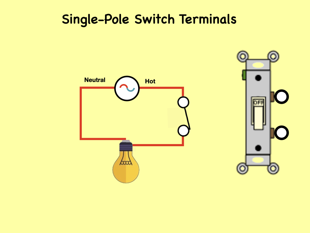
In this simple circuit, a single-pole single-through (SPST) switch has only two terminals, plus a ground screw (for newer switches). The switch terminals connect only to the hot wires in a circuit and are interchangeable, so the terminal screws are the same color. These switches don't typically connect to the neutral, so there is no terminal for the neutral wire. This is a simplistic schematic of what is going on. The hot wire is switched to the light with a neutral returning to the source.

There are two ways that a switch can be wired to control a light. First of all there will always be a two wire cable connecting the switch to the light. Let's call it the connecting cable. A two wire cable will have a black wire and a white wire and usually a ground wire. Then power has to be introduced to this circuit arrangement which is also done with a two wire cable. Let's call it the power cable. It can be either brought in to the light box which holds the light or the power can be brought into the switch box which holds the switch. Then connections are made in the boxes that hold the light and the switch.
This diagram shows the connections made inside the light box and the switch box for the situation where the power cable comes into the light box. The first thing to note is that the incoming ground wire from the power cable is connected to the outgoing ground wire in the connecting Cable. The ground wire is also connected to the light box and the switch box. There are ground screws in both of these boxes which are indicated in our diagram by a round green spot. Newer switches will have a ground screw which must be connected to the ground wires.
The white wire from the power cable is connected to one of the terminals of the light which is either a screw or a white wire.

The black wire from the power cable is connected to the white wire of the connecting cable. This white wire enters the switch box and it's connected to one of the two screws on the side of the single pole single throw switch. The black wire from the connecting cable is connected to the other screw of this switch.
The black wire from the connecting cable entering the light box is connected to the other terminal of the light which is either a screw or a black wire.

The above is an updated version of the previous arrangement. Because the electrical code as of the 2011 update may require a neutral wire in most new switch boxes, a 3-wire cable runs between the light and switch. The red and black are used for hot and the white neutral wire at the switch box allows for powering a timer, remote control, or a programmable switch.
Here a single-pole single-through switch controls the power to a light fixture. The power source is at the switch and a 2-wire cable runs from there to the light. The source hot wire is connected to one switch terminal and the other terminal is connected to the black cable wire running to the light. The neutral wire from the source is spliced to the white cable wire and continues on to the light. At the light, the white wire connects to the neutral terminal and the black wire connects to the hot terminal.

Here two switches are wired in the same double-ganged switch box, to control two separate lights. The source is at the switch box and a 2-wire cable is run to each light. One source is spliced to each switch with a pigtail to power the two lights.

The diagram to the left illustrates the wiring for a split receptacle with the top half controlled by SW1 and the bottom half always hot. The receptacle is split by breaking the connecting tab between the two, brass-colored terminals. The tab between the neutral, silver terminals should remain intact.
Here, the source is at the outlet and 2-wire cable runs from there to SW1. The circuit neutral wire is connected to one of the neutral terminals on the outlet, it doesn't run to the switch. The hot source is spliced to a pigtail that connects to the bottom, always-hot half on the receptacle and to the white cable wire running to SW1. The black cable wire runs to the SW1 connecting it to the hot on the top half of the split outlet.

In this updated diagram to the left, a 3-wire cable runs between the receptacle and switch and the red cable wire is used to carry the hot source to the switch. The neutral from the source is spliced through to the switch box using the white wire and in this diagram, the white wire is capped with a wire nut. This represents a change in the NEC code that requires a neutral wire in most new switch boxes. The white neutral wire at the switch box allows for powering a timer, remote control, or a programmable switch.
Three-way switches allow for controlling a light fixture from two separate locations, these are usually used at the top and bottom of a flight of stairs or at two different entrances to a room. Following are several wiring diagrams that can be used to map 3 way lighting circuits depending on the location of the power source in relation to the switches and lights.
Three-way switches have 3 terminals to carry circuit electricity and one terminal for a ground wire. Of the three circuit terminals, one is called the common and the other two are known as travelers. The common terminal may be labeled and is usually a different color than the traveler terminals. Depending on the manufacturer, the travelers may be on opposite sides of the device or the two terminals may be on the same side. In any case, the common terminal will be distinguished from the travelers in some way.
The common terminals will always be connected to a hot wire, either from the source or on the light fixture. These connections can be reversed if it's more convenient, as long as one of the 3 way common terminals connects to the hot source and the other one connects to the hot on the load. The traveler terminals will always be connected from switch to switch. Travelers never connect to a device load or to a source wire. It doesn't matter which traveler terminal is used for which traveler wire, reversing them will make no difference.

In the above diagram, the electrical source is at the first switch and the light is located at the end of the circuit. Three-wire cable runs between the switches and 2-wire cable runs to the light. The black and red wires between SW1 and SW2 are connected to the traveler terminals. The hot source is connected to the common terminal on SW1 and the common terminal on SW2 connects to the hot terminal on the light.

The power source in the above circuit is at the first switch and the light fixture is located between SW1 and SW2. Three-wire cable runs between each switch and the light fixture. The hot source wire is connected to the common terminal on SW1. The common terminal on SW2 is connected to the hot terminal on the light. The traveler wires are spliced at the fixture box to run between the traveler terminals on the switches, they are not connected to the light.

In this diagram, the power source for the circuit is at the light fixture and the two switches come after. Two-wire cable runs from the light to SW1 and a 3-wire cable runs between SW1 and SW2. The hot source wire is spliced at the lightbox to the white cable wire running to the first switch box. There it is spliced to the black wire running to the second switch box, which is then connected to the common terminal on SW2. When a white wire is used for hot like this, it's marked with black tape or paint at the ends to identify it as hot.
Back at the light fixture, the hot terminal on the light is connected to the black wire running to the common terminal on SW1. At SW1, the red and white wires running to SW2 are used as travellers connecting the traveler terminals between the two switches. Again, the white wire is marked with black on the ends to identify it as hot.

In this arrangement, the power source for the circuit is at the light fixture which is located in the middle of the circuit. A 3-wire cable runs to the switches on each side of the light. At the light, the hot source wire is spliced to the black wire running to the common terminal on SW2. The hot terminal on the light fixture is connected to the black wire running to the common terminal on SW1. The red and white cable wires are spliced in the fixture box and run to the traveler terminals on both switches. They don't connect to the light fixture. It is good practice to mark the white wire if it is being used as a hot wire. In this case, the white wire is marked with black tape on both ends to identify it as hot.
The following 4 graphic slides demonstrate the functioning of a 4-way switch and two 3-way switches to control lights.


Any number of these DPDS switches can be used as long as they're placed between the three way switches.

The wiring diagrams on the above slide make use of three 4 way switches located between two 3-way switches to control lights from five locations. Two wire cable is used between the power source and the first three way switch and the light in the second three-way switch. Three wire cable is used between the five switches. The red and black wires in the cables are connected to the traveler screws on the five switches. All of the white wires are spliced together in each switch box and connected to the neutral of the light. The Black hot wire coming from the source is connected to the common terminal of the first three way switch and the common of the second three-way switch is connected through the two-wire cable to the hot terminal of the light.

In this basic 4 way light circuit, a 3-wire cable runs between all the switches and a 2-wire cable runs from the last switch to the light.
The electrical source is at the first 3 way switch and the hot wire connects to the common there. The circuit neutral is spliced at each switch box through to the light fixture using the white wire. The black and red wires running between the boxes are connected to the travelers on each switch. The common terminal on the 3 way switch at the end of the circuit connects to the black wire running to the hot terminal on the light.
Take note that the traveler wires from SW1 are connected to the T1 pair on the 4 way switch and the travelers going to SW2 are connected to the T2 pair. Each pair of traveler terminals on the 4 way must be connected to only one 3 way switch. Don't mix up the pairs or the circuit will not work properly.

Here two 4-way and two 3-way switches are used to control lights from four different locations. The two 4-ways are located between the two 3-way switches.
Two wire cable is used between the power source and the first three way switch and the light in the second three-way switch. Three wire cable is used between the four switches. The red and black wires on the cables are connected to the traveler screws on the four switches. All of the white wires are spliced together in each switch box and connected to the neutral of the light. The Black hot wire coming from the source is connected to the common terminal of the first three way switch and the common of the second three-way switch is connected through the two-wire cable to the hot terminal of the light.
Blog #9 - Residential Electrical Power Chapter Four
/Residential Electrical Power Chapter Four
Low Voltage Circuit Wire & Cable

In the world of building wire, there are several common choices available that at first appear quite similar. Some of the most common of them; THHN, THWN, and Romex.
THHN WIRE is Thermoplastic High Heat-resistant Nylon-coated wire that is a single conductor wire with PVC insulation and a nylon jacket. It’s commonly used in conduit as electrical wire for buildings. Its heat and oil resistance makes it suitable for appliances and machine tools.
THWN is essentially the same as THHN and the two are often used interchangeably. THWN is also a single conductor wire with PVC insulation and a nylon jacket. The key difference is the “W” in the name which indicates water resistance. THWN is rated for temperatures up to 90°C in wet conditions vs 75°C for THHN.
Romex wire refers to the trade name for Thermoplastic-Sheathed Cable (TPS). Romex is often used as residential wiring for electrical circuits and lighting. We generally think of a specific type of Romex, which is known for its nonmetallic sheathing and primary use as branch wiring. This is referred to as Romex NM-D or B.

Recently, Nexans Canada introduced colour coding to its line of non-metallic sheathed cables to enable easy identification of the various sizes commonly used in residential construction. These copper conductor cables are used mainly to distribute power to outlets, lights, electric ranges, dryers, and other equipment. This type of cable is commonly known by trade names such as Romex or Canadex, but the Canadian Standards Association type is NMD90, meaning non-metallic, dry location, 90 degree Celsius rated.
Nexans now supplies NMD cable with coloured jackets. Cable for use with 15 ampere AFCI is supplied with a blue jacket, and the cable for use with a 20-ampere kitchen GFCI has a yellow jacket. As well, two conductor No. 14 AWG copper NMD used for other 15-ampere circuits is supplied with a white jacket, all No. 12 AWG copper for 20-ampere circuits has a yellow jacket, all No. 10 AWG copper for 30-ampere circuits has an orange jacket, and cables for over 30 amperes have a white jacket.
The jacket colour coding is not required by any electrical code or by CSA product requirements. However, Nexans supplies the colour-coded products as an aid for installers and inspectors in identifying cables used to supply the two special types of circuits mentioned above and to indicate copper conductor size. In doing so Nexans makes the job of cable identification quick and accurate for the contractor and inspector.

NFPA 70 National Electrical Code
(NEC)
2020 Edition 1st Edition
by (NFPA) National Fire Protection Association
Based on the 2020 National Electrical Code (NEC), the National Electrical Code Handbook clarifies concepts for a better understanding of the Code. It's a powerful communication tool that helps you explain the NEC to clients and others who might not have professional electrical training.
Voltage drop is the reduction in voltage in an electrical circuit between the source and the load. Wires carrying electricity have inherent resistance, or impedance, to current flow. Voltage drop is the amount of voltage loss that occurs through a circuit due to this impedance.
For equipment to operate properly, it must be supplied with the right amount of power, which is measured in watts which is calculated by multiplying current (amps) x voltage (volts). Motors, generators, lights — anything that runs on electricity — is rated for power. The correct amount of power enables equipment to meet its designed power rating and operate efficiently. Too much or insufficient amounts of power can result in inefficient operation, wasteful power usage, and even equipment damage. That is why understanding voltage drop calculations and selecting the correct cable for each application is so important.
The National Electrical Code (NEC) catalogs the requirements for safe electrical installations and represents the primary document for guidance. Providing direction for both trained professionals and end users, these codes set the foundation for the design and inspection of electrical installations. For branch circuits, look to NEC advises that conductors for feeders to dwelling units should be sized to prevent voltage drop exceeding 3% and maximum total voltage drop on both feeders and branch circuits should not exceed 5% for “reasonable efficiency of operation.”
In addition, when dealing with sensitive electronic equipment. It states that voltage drop on any branch circuit shall not exceed 1.5% and the combined voltage drop on branch circuit and feeder conductors shall not exceed 2.5%. It is important to note that much of the equipment manufactured today contain electronics that are particularly sensitive to excessive voltage drop.
Ampacity, a cable’s electric current-carrying capacity, is also connected to voltage drop. Electrical Codes stress the importance of accounting for voltage drop when considering a cable’s ampacity rating and the need to satisfy both requirements.
In order to understand voltage drop let’s consider the simple circuit in the diagram to the right. A voltage source of 110 Volts AC is connected to a load resistor of 11 Ω. According to Ohm's Law the current that will be drawn by the load will be equal to the voltage divided by the resistance, which in this case will be 10 Amps.


Looking at the same components, but this time with two 11 Ω resistors in series with each other. We still have a voltage supply of 110 Volts and Ohms Law tells us that current will be 5 Amps and the voltage drop across each resistor will be 5×11 for 55 Volts.
Let's add eight more resistors, and reconfigure the circuit to look like this. The current in a circuit will now be a function of the supply voltage divided by the total resistance which is made up of ten 11 Ω resistors. Using Ohms Law to obtain a current in a circuit we use the supply voltage, divided by the total resistance; substituting actual values we get 110 volts divided by 110 Ω or 1 amp.
We can easily calculate the voltage drop across each resistor now by multiplying the current times the individual resistance of 11 Ω which works out to 11 Volts.


Now let's add a load of 10 Ω to the circuit. The total load now becomes the 10 resistors plus the 10 ohms of the load. The current of the circuit is now given by 110 Volts divided by 110 ohms plus the load of 10 Ω which equals 0.92 Amps.
This time we are interested in the voltage drop across the 10 Ω load which is given by the current times the 10 Ω load which equals 9.2 Volts.
Let's add some realism to the situation and suppose that the load is a 100 W incandescent light bulb.

The equivalent load existence of the 101 light which is essentially just a resistor that emits light and heat, is given by the equation. Plugging in the actual values of the lightbulb if it is connected to 110 volt power supply, the equivalent resistance would be 121 Ω.
I am making one other change to our circuit and that is I'm going to change each of the individual resistors “R” to 0.25 Ω. That means the calculated circuit current will be 110 volts divided by the total resistance of 2.5+121 which equals 0.89 Amps. With that amount of current flowing in the circuit, the voltage drop across our lightbulb will be 0.89×121 which equals 107.8 volts. This is interesting now, because the lightbulb was rated at 100 W which was calculated for a supply voltage of 110 volts.


The physical make up of the lightbulb has not changed, which means our calculated resistance also has not changed, it is still 121 Ω. In our circuit, the voltage drop across the lightbulb has been calculated at 107.8 volts and the current in a circuit has been calculated at 0.89 amps, therefore the lightbulb will be the dissipating 95.9 W. This means that the output light will be reduced in brilliance by about 4 percent.
The total resistance in the circuit of 121 Ω is the same as connecting a power source to the lightbulb with a length of #14-2 AWG copper wire. This points out the fact that even copper wire has some resistance, which does become significant over some distance. Although a 4% drop in light bulb brilliance is not that significant, given more lightbulbs or more length of wire, the percentage drop across each lightbulb will decrease to a point where it starts to be significant. This becomes even more significant if the load were a motor, such as a water pump because the voltage drop across the pump is made up of both resistance and “Back EMF”. The back EMF of a motor is related to its speed of rotation, which is related to the applied voltage, so the drop in voltage is not just 4%, as in the case of a pure resistive load.


Instead of the load being purely resistive, let’s replace it with a motor whose back EMF and internal resistance provide the same voltage drop as the 10 Ω load did

This means that the voltage drop will be greater than 4%, which ultimately means more current is going to flow for the same amount of work that is being done. Over time, and depending on the time, this means the windings of the motor will begin to heat and ultimately overheat, causing damage to the motor.
Taking into consideration the characteristics of a motor, the reduction in voltage may mean that the speed of the motor does not have enough energy to get past the inrush current, exacerbating the whole situation.

Blog #8 - Residential Electrical Power Chapter Three
/Residential Electrical Power Chapter Three
Low Voltage Circuit Protection

American wire gauge (AWG), also known as the Brown & Sharpe wire gauge, is a logarithmic stepped standardized wire gauge system used since 1857, predominantly in North America, for the diameters of round, solid, nonferrous, electrically conducting wire. The cross-sectional area of each gauge is an important factor for determining its current-carrying ampacity.

Low Voltage wiring will involve the requirement of different sizes or gauges of wire depending on the load that it feeds or more precisely, the amperage it will have to carry. Wire sizes are categorized by what is standard in North America as the American Wire Gauge. This is a measure of wire thickness (which also dictates cross-sectional area, and for a given material, ampacity). For example…24 AWG wire has a nominal diameter of 0.0201in or 0.511mm. AWG only applies to wire used to conduct electricity.

These above two charts describe the characteristics and capabilities of the various wire gauges of copper wire.The chart with the white background is the current caring capacity of the various copper conductors…for example for a load that draws 15 amps #14 AWG wire is required. The chart with the green background, along with describing the diameter indicates the resistance of the wire in ohms per foot. This is only significant for long runs of cables.

Due to the current carrying capacity of the various gauges of wire sizes, the figure on the left shows the breaker rating and type, single pole single throw (SPST) and single pole double throw (SPDT), required for the various wire gauges.

Circuit protection is employed to protect wires and electrical equipment from damage in the event of an electrical overload, short circuit, or ground fault. Lightning storms, overloaded power outlets, or a sudden electrical surge may result in a dangerous situation with the potential to cause fire, equipment damage, or personal injury. Circuit protection is designed to eliminate this risk before it occurs by cutting off the power to the circuit.
A circuit breaker is a protection device employed in every electrical circuit to prevent any potential hazard. There are different types of circuit breakers used all over the world due to their various characteristics & applications. It is necessary to have a circuit breaker that offers adequate protection so that one can work safely around it without having fear of any potential hazards. That is why it is best to know about these kinds of circuit breakers & what kinds of protection do they offer before buying one.

A circuit breaker breaks the circuit in case of overloading & short circuit. The fault currents generated due to these fault conditions can damage the electrical devices as well as cause fire in a building that can also pose danger to human life. The circuit breaker instantly cut off the power supply to reduce further damage.
A circuit breaker has two types of tripping units i.e. a thermal unit and a magnetic tripping unit.
The thermal tripping unit is used for protection against overloading. It uses a bi-metallic contact that bends with a change in temperature. The current flowing through the bimetallic strip heats up contact & trips the circuit breaker. The rate of bending of the bi-metallic strip depends on the amount of current. Therefore, the greater the overloading current, the faster the circuit breaker trips.
The magnetic trip unit is used for protection against short circuit current. It includes a solenoid that produced a strong magnetic field due to a high short circuit current to instantly trip the circuit breaker.
The expected behaviour of a circuit breaker depends on its design and what it is designed for. This behaviour is best described by a Trip Curve.

A trip curve is a graphical representation of the expected behaviour of a circuit breaker. Trip curves plot the interrupting time of circuit breakers based on a given current level. They are provided by the manufacturers of circuit breakers to assist users with selecting breakers that provide proper equipment protection and performance while avoiding nuisance tripping.
To avoid nuisance trips, circuit breakers need to be sized appropriately to compensate for inrush current. NEMA defines instantaneous peak inrush as the momentary current transient that occurs within half an AC cycle after contact closure.
Inrush current is what causes lights to dim in a house when a motor, such as that on a clothes dryer or vacuum cleaner starts up.
We need different trip curves in order to balance the right amount of overcurrent protection against optimal machine operation. Choosing a circuit breaker with a trip curve that trips too soon can result in nuisance tripping. Choosing a circuit breaker that trips too late can result in catastrophic damage to machine and cables.

The three most common trip curves for Miniature Circuit Breakers are B, C and D. By putting all three on one chart, we can see how the thermal portion of the curves are similar to each other, but there are differences in how the magnetic curve, and thus the circuit breaker functions.
The tripping curve tells how fast a circuit breaker will trip at a specific current. The different tripping curves classify the circuit breakers into categories where each category is used for specific types of loads. It is essential to select a circuit breaker that provides the necessary overcurrent protection.
Type B circuit breakers are designed to instantly trip when the operating current is 3 to 5 times its rated current. Their tripping time falls between 0.04 to 13 seconds. They are suitable for domestic applications where surges are very low such as lighting, small motors & resistive loads.
Type C circuit breakers trip instantly at current surges 5 to 10 times its rated current. Its tripping time lies between 0.04 to 5 seconds. As they can tolerate higher surge currents, they are used in commercial applications such as the protection of small motors, transformers, etc.
Type D circuit breakers trip instantly when operating currents reach 10 to 20 times their rated current. Its tripping time is 0.04 to 3 seconds. Such circuit breakers can tolerate the high inrush current of large motors. Therefore, they are suitable for running heavy loads in industrial applications.

According to NEC (National Electric Code), IEC (International Electrotechnical Commission) and IEEE (Institute of Electrical and Electronics Engineers), a proper size a circuit breaker is a must for all electrical circuits i.e. residential wiring and industrial or commercial installation to prevent the electrocution, hazardous fire and protection of the connected electrical equipment and appliances.
For maximum safety and reliable operation of the electrical machines, it is recommended to use the correct and suitable size of the circuit breaker according to the circuit’s current flowing through it. If we don’t use a correctly sized circuit breaker. In case of other (over or lower) sizes instead of the correct-sized circuit breaker, the circuit, cables and wire even the connected device may heat up or in case of a short circuit, it may start to smoke and burn. That’s why a correct size circuit breaker is needed for smooth operation.
Under normal conditions when the circuit current rating is lower than 80% of the circuit breaker rating, the circuit operation is normal and the circuit breaker will not trip. In case of fault or short circuit when the value of current exceeds the circuit breaker rating, It will automatically trip i.e. break the circuit from the supply.
For example, a 30 amp circuit breaker will trip at or above 30 amp no matter if is it a continuous or noncontinuous load. However, just after the current exceeds 80%, of the circuit breaker rating, even buy a small amount, the thermal element of the breaker will start to heat up and if the current does not drop below 80%, but continues to flow the breaker will eventually trip after a long period of time.
That’s why we must select 20-25% higher for circuit breaker rating than the expected, flowing current in the cables and wires to the connected device.
In order to determine the appropriate size of circuit breaker for single phase supply, it depends on multiple factors, like the type of load, cable material and even the environment temperature.
The general rule of thumb is that circuit breaker size should be 125% of the ampacity of cable and wire or the circuit which has to be protected by the circuit breaker. Let see the following solved examples:
Example# 1
Suppose, a 12 gauge wire is used for 20 amperes lighting circuit having 120V single phase supply. What is the best size of circuit breaker for that 20 A circuit?
Solution:
Circuit Current: 12A
Circuit Breaker size should be 125% of the circuit current = 125% x 20A
Circuit Breaker Size = 25A
Example #2
What is the appropriate size of circuit breaker for 2000W, single phase 120V Supply?
Solution:
Load: 2000W
Voltage: 120V (Single Phase)
Circuit Current: I = P / V
I = 2000W / 120V
I = 16.66 A.
Circuit Breaker Size: 1.2 or 1.25 to the load current.
1.2 x 16.66 A
Circuit Breaker Size = 20 A.
Circuit protection is employed to protect the wires and electrical equipment from damage in the event of an electrical overload, short circuit, or ground fault. Lightning storms, overloaded power outlets, or a sudden electrical surge may result in a dangerous situation with the potential to cause fires, equipment damage, or personal injury. Circuit protection is designed to eliminate this risk before it occurs by cutting off the power to the circuit. Circuit protection devices include fuses, miniature circuit breakers, molded case circuit breakers, supplementary protectors, motor protection circuit breakers, overload relays, electronic fuses and air circuit breakers.
Trip Curves predict the behavior of circuit protection devices in both slower, smaller overcurrent conditions, and larger, faster overcurrent conditions. Choosing the correct trip curve for your application provides reliable circuit protection while limiting nuisance or false trips.
This blog is a brief overview of circuit breakers. It is not intended to be the final answer on this topic. There is a lot more to learn, including other types of trip curves and circuit breaker coordination. With the basics now covered, one can confidently approach those topics.
Blog #7 - Residential Electrical Power Chapter Two
/Residential Electrical Power Chapter Two

This blog is designed to give the reader an introduction to the low-voltage electrical wiring found in residential homes. Most of it applies to any installation that uses a 120/240 AC volt supply. Of course, there are numerous permutations and combinations involved, but this blog will explain the most used and generally, familiar to the public situations. It is designed around the national electric code (NEC) but codes vary depending on where you are in North America and indeed the world. As a disclaimer, I am going to say that some of the wiring and some of the statements may not apply to local electrical codes. In order to be sure, the student should check with the local authorities first, prior to changing any wires wiring in their homes. At the very least this blog will provide a starting point.


This first chapter will cover some of the essential rules that we will follow when justifying some of the circuitry to be found later. The first thing that is to be known, is that all functioning elements form electric circuits and current will flow from positive to negative in a circular fashion around a loop regardless if we are using AC or DC power sources. All electric circuits have Voltage, Current and Resistance that are related by Ohm's Law which states that the current in a circuit will very directly as the voltage and inversely as the resistance in the circuit. In this illustration, current will flow in a circuit formed by the wires connecting the battery through the lightbulb back to the battery. The voltage of the source equals the voltage drop across the lightbulb in this case 120 Volts.
Of course, batteries don't operate household systems. It is AC current that is changing polarities 60 times a second (in North America). The filament in the lightbulb does not get a chance to cool in between the cycle changes, hence the light looks like it's on steady, which indeed it is. The use of AC current is mainly because it allows for voltage transformation. That is, to be stepped up and transferred over long distances and then stepped down to lower levels to make it useful and safe within homes.
Let’s have a closer look at this changing polarity of 60 times a second. If we look at the voltage in the system it starts at “0” rises to a maximum then reduces back to “0” and proceeds to a negative maximum then goes back to “0” again. It repeats itself every 1/60th of a second. It does this in what is called a “sinusoidal” shape, as you see here in blue.For simplicity we will assume that most loads are resistive in nature (lightbulbs, baseboard electric heaters, electric stoves and ovens, etc.) Therefore, the instantaneous current in the circuit will follow the voltage and it too will be “sinusoidal”. We say that it is “in-phase” with the voltage, as you see here in red.The question now becomes…How do we describe the magnitude of this sinusoidal voltage and current, if it is continuously changing?…There are several ways.

We can measure and compare the amplitude or peak…Another way is to measure and compare the peak to peak. Still another way, is to average the curve…but that would just be “0”…not too useful…Unless we squared the value first, then found the square root. This would essentially change the shape of the curve placing all of the curves above zero. Now we could average the value of this voltage or current and it would be a positive value and greater than “0”. This value is known as the “Root-Mean-Square” or RMS value of the voltage and current and it is exactly the square root of 2 or 0.707 times the peak value.

This averaging is the equivalent of shaving off the areas of the peaks of the curve above the RMS line, (the mauve dotted line) which would exactly fill the space between the curves below the RMS line. This may seem like a bit of mathematical manipulation, however as it turns out it is very useful in calculating the average power and energy consumed by a customer. And as a matter of fact, all AC current and voltages are measured in RMS values and all voltmeters, ammeters, and multi-meters, unless otherwise stated are registered in RMS values. If you have a closer look at the average quality of the voltage overtime here it is exactly what the DC voltage would look like and in fact RMS values are often referred to as the DC equivalent of AC voltage and current.

The RMS values of current and voltages are used in calculating the average power and energy consumed. The power draw that a load such as a lightbulb takes from the circuit is expressed in watts. The load in power rating is usually marked on the device such as a lightbulb and in this case, it is 100 Watt bulb. The power in watts consumed by a load is given by the current times the voltage (using RMS values) or W = I x V.
Because the current in a circuit is equal to the voltage divided by the resistance, then we can rewrite the equation for watts in either of the following two ways… as depicted in the graphic above.
As a final note, the standard symbol for an AC generator is not a two-ended battery but a simple circle with a sinusoidal wave shape.

Quite often we have to calculate the current that a specific load will draw given its rating in watts and we know the connected voltage. In that case we will use the first equation re-written. For example, if the load were a 100 Watt incandescent light bulb. and we know that the connected voltage is 120 V. Then the connected current is 100/120 or 0.83 Amps.
Now if the load were not a 100 Watt incandescent light bulb but a 1 kilowatt heater and the connected voltage is still 120 V. Then the connected current is 1000/120 or 8.33 Amps.

Keeping the load of a 1 kilowatt heater and change the connected voltage to 240 V. Then the connected current is 1000/240 or dropping the current to 4.17 Amps. This time the 1 kW heater is rated at 240 V not 120 V.

Looking at the power panel and the incoming connections from the utility.
Measuring the voltages over time…Remember, voltage is a measurement of the potential difference between two points. Let’s measure that voltage over time starting with the potential difference between the hot terminal “A” with respect to the neutral. As you see it rises to a maximum of 120 V positive then returns to zero and goes to -120 V and back to zero and repeats itself. It will do this 60 times a second. Repeating the measurement this time of the hot terminal "B" with respect to the neutral. As you see it rises to a maximum of -120 V and then returns to zero and goes to +120 V and back to zero and repeats itself. It will do this 60 times a second. As is evident from this time measurement, the voltages are, at all times, out of phase with each other. In fact, they are 180° out of phase with each other. That means if we take the measure of the potential difference between the two hot terminals. The potential difference between the two hot terminals “A” & “B” with respect to each other, rises to a maximum of 240 Volts positive then returns to zero and goes to -240 V and back to zero and repeats itself 60 times a second. In this way, the utility can supply both 120 V and 240 V to this customer.

Blog #6 - Residential Electrical Power Chapter one
/Residential Electrical Power Chapter one

This blog covers general information about what you will generally find in North American residential electrical power systems. It is focused mainly on theoretical and observational information. It is not a comprehensive guide to regulations or safety requirements. For any “do it yourself work” you are encouraged to consult with your local utility and safety regulations before starting any work.

Connecting homes to the electrical grid is the final stage of the electrical grid. After the distribution grid's substations have stepped-down the voltage to safe levels, this stage may be accomplished. Wires lead off from the neighbourhood's power lines and connect to individual buildings (homes, apartments, businesses,) by first going through the electric meter to measure how much electricity the home uses. The electricity then passes through a service panel, which houses the electrical safety devices (circuit breakers or fuses). This service panel has all of the wires that run to the different electrical appliances around the house.
Every home is connected to the electrical grid through some sort of fuse box or circuit breaker.
The overhead power connection from the utility lines to the service entrance is referred to as the service drop. It has three wires. One neutral line and two hot lines. The hot lines maintain a certain potential (like 120 V) compared to the neutral line. There are two types of overhead service drops, a mast service drop, or an underground service connection.
The service connection enters the panel via the main disconnect breaker, which is utilized during emergencies to stop electrical power flow. This is positioned in between the service meter and the rest of the electrical panel. The main disconnect is a circuit breakers housed in the electrical panel. In order for this to work the circuit breakers must be in series with the two hot lines of the conductors because it must cut power to all circuits. It is rated to be able to interrupt the total household load.

This diagram to the right, illustrates some of the most common circuits found in a typical circuit breaker service panel box. The breakers are installed in a panel so that contact is made with one or both of the hot bus bars running down the middle of the box. The hot wire for a branch circuit is connected to the breaker by a set screw on the base. The neutral and ground wires for the circuit are connected to a bar along the side of the service panel box. The neutral and grounding bars in the panel may be separate or, in the case of older service panels, the same bar may be used for both purposes.
This wiring diagram illustrates installing a 15 amp circuit breaker for a 120 volt branch circuit. The 14/2 awg cable for this circuit includes 2 conductors and 1 ground wire. A 15 amp circuit is usually used for wall receptacle outlets and room light fixtures.

Since most appliances are designed to operate with 120 V, such as the lighting and outlet recepticles, they are connected to the 120-V lines as in Circuits #1 & #2. Larger appliances requiring 240 V, are connected as in circuit #3.
To avoid trouble, insulation, grounding, fuses, and circuit breakers are used. Modern wiring codes require a third wire for a separate ground.
Because of the dangers of electricity, house wiring is carefully regulated by a code drawn by local ordinances and by the National Electrical Code (NEC).


Electrical outlets provide a means of connecting various devices which require electricity. There are many different types of outlets around the world, with varying voltage and electric current properties. Some are shown here.

As of the 2011 NEC, most new and replacement receptacles must be tamper-proof. This requirement is designed to protect small children from injury by preventing the insertion of objects, other than electrical plugs, into the receptacle contacts. Some exceptions to this requirement include wall receptacles that are more than 62 inches from floor level and large appliance receptacles located out of reach.
New wall receptacles will have two types of contacts: terminal screws on the sides, and holes in the back. The screws may be designed to secure a hooked wire to the device when driven home, or they may be used to tighten a clamp around the end of a straight wire.
The holes in the back of the device are used for inserting a straight wire into an internal clamp. The holes will be labeled to indicate what wire size they can accept.
Receptacles are available for 15 and 20 amp ratings. In older homes, the devices and wiring may be outdated and you will find receptacles that are ungrounded or even ungrounded and non-polarized.

This is a standard 15 and 20 amp, 120 volt wall receptacle outlet wiring diagrams. This is a polarized device. The long slot on the left is the neutral contact and the short slot on the right is the hot contact. A grounded contact at the bottom, center is crescent shaped. The hot screws are usually a brass colour. Neutral screws are usually silver in colour and ground screws are usually green.
The 15 amp, 120 V duplex receptacle outlet can typically be found in livingroom and bedroom wall outlets. One of these may be controlled with a switch and/or wired to other outlets in the circuit. For a 15 amp receptacle like this, 14/2 cable with ground should be used to feed the circuit.
A 20 amp, 120 V duplex receptacle outlet like this should be installed in a circuit using 12 awg cable and a 20 amp circuit breaker. These receptacles are usually found in kitchen wall outlets where two branch circuits are needed to serve small appliances and a refrigerator separately.
When using this device for heavy appliances like washing machines and microwaves, it should be connected to a dedicated 20 amp/120 V circuit breaker. Some electrical codes require circuits to be protected from Arc faults. This can be accomplished with the use of AFI breakers.

An AFI or Arc-Fault Interrupter, is a circuit breaker that breaks the circuit when it detects an electric arc that is a signature of loose connections in home wiring. Loose connections, which can develop over time, and can sometimes become hot enough to ignite house fires.

A residual-current device (RCD), residual-current circuit breaker (RCCB) or ground fault circuit interrupter (GFCI) sometimes simply refered to as a GFI, is an electrical safety device that quickly breaks an electrical circuit with leakage current to ground. It is to protect equipment and reduce the risk of serious harm from an ongoing electric shock.
These electrical wiring devices are designed to quickly and automatically isolate a circuit when it detects that the electric current is unbalanced between the supply and return conductors of a circuit.
They are designed to disconnect the conducting wires ("trip") quickly enough to potentially prevent serious injury to humans, and to prevent damage to electrical devices.
RCDs are testable and resettable devices. A test button safely creates a small leakage condition, and another button resets the conductors after a fault condition has been cleared.
This leakage can be detected either at the receptacle itself (self-contained GFI protection) or back at the power panel with a special breaker that will protect the whole circuit (circuit breaker GFI protection). The above drawing shows how both of these receptacles are connected.
This is the first entry for
Low Voltage Residential Wiring…more to follow

Blog #5 - Electrical Grounding
/

Grounding is a principle of electricity that sometimes puzzles homeowners. To understand its importance to a home wiring system, it is important to know something about the nature of electrical energy flow.
What Is Electrical Grounding?
Grounding offers excess electricity the most effective and safest route from an appliance back to the ground by way of an electrical panel. Electrical grounding is a backup pathway, that is generally only used if there is a fault in the wiring system.

Electrical service to North American homes began in the late 1890’s, and blossomed from 1920 to 1935, by which time, 70 percent of homes were connected to the electrical utility grid.
In the following 200 years, the methods for installing wiring in those homes has seen several important innovations, aimed at improving the safety of electrical systems.

Between eighteen 90 and 1910, a wiring system known as knob-and-tube, was the principal system of installation. It was quite a dependable system for the time, and a surprising number of homes still have knob-and-tube wiring functioning, where it is often found alongside more modern updates. In knob-and-tube wiring, individually conducting wires protected by a rubberized cloth fabric, are installed in stud and joist cavities, held in place by porcelain knob insulators, attached to the sides of framing members, and protected by porcelain tube insulators where the wires run through, the framing members.
In this wiring system, hot wires, and neutral wires, were run separately for safety. The system also allowed long circuit runs to be constructed by splicing together lengths of wire. To do this, the insulation was stripped back, a new wire was wrapped around the exposed bare wire, and the splice was soldered together then taped to cover the splice.
The downfall was the wire was exposed and there was no ground wire used. Where knob-and-tube wiring is still functioning, it is living on borrowed time, since the rubberized cloth insulation used on the wires has an expected lifespan of about 25 years, before it begins to crack and break down.
Electrical systems containing functioning knob-and-tube wiring are in critical need of an upgrade. But just because you see knob-and-tubes in some wall or floor cavities, doesn't necessarily mean you are in danger.
It was common practice to simply leave old wiring in place, but not energized, and functionally replaced when a home was rewired.
It's possible that the porcelain insulators and wires you see are merely antique remnants of earlier wiring installation.
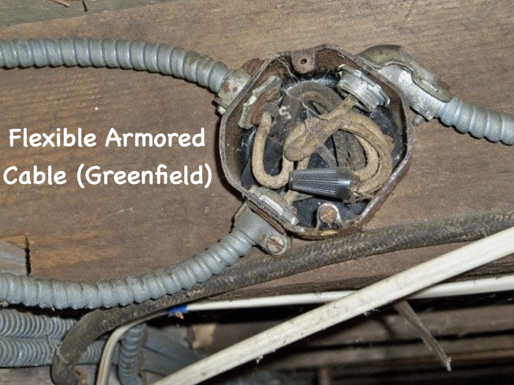
In the 1920s to 1940s, electrical installations took a turn to a more protective wiring scheme, flexible armored cable or Flex, also known as Greenfield, was a welcomed addition to home wiring because the flexible metal jacket helped to protect the wires from damage, and also offered a metal pathway that could ground the system, when properly installed.
Although it was an improvement, this wiring method had its troubles. Although the individual wire conductors are protected, the flexible outer metal jacket serves as a proper ground only when the metal pathway is complete, all the way to the service entrance and grounding rod. There is still no separate ground wire in these installations.

Nonmetallic Sheathed Cable

In the 1930s, a quicker installation method was developed. Nonmetallic-sheathed cable was born, which incorporated a rubberized fabric coating sheath, much like knob and tube wiring, but here the hot and neutral wire were run together in this one sheathing. It also had its drawbacks due to the lack of a ground wire, but its development would eventually lead to major innovations.
Early sheathed cable, however, also has an expected lifespan of about 25 years, and where it is still in use, such installations need to be upgraded.
The Age of Metal Conduit
The newest addition to wiring was NMD, introduced in around 1965. This form of NMD cable was an update to older NM cable and incorporated the use of a bare copper grounding wire along with the insulated hot and neutral wires, contained within the sheathing. Instead of rubberized sheathing, modern NMD cable uses a very tough and durable vinyl sheathing. This update made the cable inexpensive and very easy to install. It is a very flexible product and is used extensively in virtually every new home built.

Along with NMD cable for interior use, a related type of cable was also developed for underground use. Underground feeder wire, (UF), can be buried directly under the ground without the need for a protecting conduit. This type of wire has a hot, a neutral, and a ground wire embedded in a solid plastic vinyl sheath that protects it from moisture. This offers an inexpensive method for running power underground to outbuildings and yard lights.

Through most of the history of residential electrical service, the preferred metal used in the conducting wires has been copper, known as the best conductor of electrical current. In the mid nineteen 60’s, when copper prices were quite high, aluminum came into vogue, as a material for electrical wiring. Residential installations between 1965 and 1974, sometimes used wires that were solid aluminum, or aluminum covered with a thin layer of copper.
Aluminum or copper-coated aluminum wiring is perfectly safe, if connected to receptacles, switches, and other devices, rated for use with aluminum, but it can pose problems, when it's installed with devices intended for use with copper wiring only.
Because of these issues, aluminum or copper-clad aluminum is no longer used in residential applications. It is for this reason, if you have aluminum wiring, repairs are best made by a professional.

To prevent electrical danger, your home's electrical system includes a backup plan, a system of grounding wires that runs parallel to the hot and neutral wires. It provides an alternate pathway for electrical current to follow should there be a breakdown in the system of hot and neutral wires, that normally carry the current. If a wire connection becomes loose, for example, or a rodent gnaws through a wire, the grounding system channels the stray current back to ground by this alternate pathway, tripping the breaker, before it can cause a fire or shock.
The grounding pathway is generally formed by a system of bare copper wires, that connect to every device, and every metal electrical box in your home.
In standard sheathed NM cable, this bare copper wire is included along with the insulated conducting wires inside the cable. The bare copper grounding wires terminate, in a grounding bar in your main service panel, and that grounding bar is in turn connected to a grounding rod driven deep into the earth outside your home.
This grounding system provides a path of least resistance for electricity to follow back to ground, should a break in the wiring system allow electricity to "leak" out of the preferred system of black and white circuit wires.
In most home wiring systems, evidence of the grounding system can be seen at each outlet receptacle, where the third round slot in the face of the receptacle represents the grounding connection. When a grounded appliance plugs into such a receptacle, its round grounding prong is now directly connected to the system of bare copper grounding wires inside the house circuits.
Not all homes have this elaborate and complete grounding system formed by a network of bare copper wires. While such a grounding system is standard in homes with circuit breakers that are wired with sheathed NM cable, older wiring systems installed before 1965 may be grounded through metal conduit or metal cable, not bare copper grounding wires. And even older systems installed before 1940 may not have any form of grounding at all. Such is the case in knob-and-tube wiring, where there is no grounding path of any kind. Many older systems have already been updated, and it is a good idea to have it done if your wiring is of this older generation. One clue that your wiring is old is when the outlet receptacles have two slots rather than three. This indicates the outlets may not be grounded.

Blog #4 - High Voltage Electrical Safety
/This post was gathered in part from a post on the Health, Safety, Security and Environment World (https://hsseworld.com/high-voltage-electrical-safety/)
While electrical power training, working safely around high-voltage conductors will be a challenge for many trainees as it is for workers. High-voltage systems are generally associated with utility services and heavy industry, such as pulp mills, sawmills, and mining operations. With care and precise planning, you can operate equipment and tools safely around these potentially lethal power lines.
This post is designed for workers who must work close to high-voltage equipment and conductors. It explains why high-voltage systems are dangerous. It lists the minimum distances you must keep away from live power lines and explains what you should do if you can’t maintain these limits of approach. It also describes common problem areas and gives safe work practices for working close to overhead lines around construction sites and for operating equipment around power lines.

Identifying High-Voltage Overhead Conductors
Overhead high-voltage conductors are usually installed at the top of utility poles. If there is more than one conductor, they are usually placed side by side on a cross arm. If there is a transformer on the pole, the high-voltage conductors are mounted above it. These are general guidelines. Employers are responsible for accurately determining the voltage of all conductors on the pole or in the work area.

An H-frame configuration may be used to facilitate the installation of transformer bank platforms on older systems. They are most often seen in alleys. This illustration shows a common single-pole configuration.
Electrical Distribution System

Electricity is transmitted from generating stations and substations via high-voltage transmission lines at 60–500 kV (60,000–500,000 V). These lines are located on top of large towers or poles in transmission rights-of-way. The voltage is reduced at substations in urban areas and distributed by overhead or underground distribution lines. The high-voltage lines on utility poles on our streets are typically at 4–25 kV (4,000–25,000 V).
Why Energized High-Voltage Systems are Dangerous
Accidents involving high voltages can result in severe injuries and death. When an electric current passes through the body, it generates heat and can extensively damage internal tissues. In some cases, the entry and exit wounds are so severe that a foot or hand has to be amputated. The electric current can also stop the heart.
Electricity seeks all paths to the ground. That path might include a tree, mobile equipment, or the human body. If a part of the equipment you are operating contacts a live power line, then anything in contact with your equipment will also become energized. The earth itself could become energized for some distance around your unit. Similarly, the ground could become energized if a tree makes contact with a power line or if a broken power line falls to the ground.
When the electrical flow reaches the ground, it spreads out like ripples in a pool of water. The voltage is very high where electrical contact is made with the ground. Farther away from this point, the voltage gradually drops off. Wet ground will extend the distance and the danger.
The voltage at the contact point is approximately the same as the line voltage. With power lines up to and including 60 kV (60,000 V), the voltage drops to zero about 10 m (33 ft.) away from the contact point with the ground. With higher voltages, such as those carried by the lines along transmission rights-of-way, the voltage might not drop to zero until you are as far away as 32 m (105 ft.).

If anything touches a high-voltage power line or if a power line falls to the ground, electricity will flow to the ground, energizing the tree or equipment and anything in contact with it. The surrounding ground may be extremely hazardous. The voltage gradually decreases from the point of contact until it reaches zero. The safe distance shown here — 10 m (33 ft.) — is for line voltages up to and including 60 kV (60,000 V) Whenever there is a voltage difference between one point and another, a current will flow. It is this flow of electricity (the current) that can cause serious injury or death.
Step Potential
Step potential is the voltage difference between two places that are a step apart on energized ground. For example, if you are standing on energized ground, there could be a significant difference in voltage between where one foot and the other are placed, and an electric current could flow up one leg and down the other.

Step potential: If your feet are spread apart on energized ground, electricity can flow through your body from the area of higher voltage to the area of lower voltage. If your feet are close together and touching, you are fairly safe. Since there is almost no voltage difference between the places where your feet stand, there is little reason for electricity to seek a path through your body. If you find yourself on energized ground and need to move away, you can avoid electric shock or electrocution because of step potential by making sure there is no space between your feet. Shuffle your feet while moving out of the energized area. When shuffling, keep your feet touching at all times to maintain the same voltage in both feet. Similarly, rescue workers must not enter an area that might be energized. Anyone trying to reach an injured worker in an energized area would be exposed to the same danger of step potential. The power lines must be de-energized and grounded before rescue workers or first aid attendants approach.

If you must move on energized ground, shuffle while keeping your feet together and touching each other. Don’t take steps.
Touch Potential
Touch potential is another danger that comes from the difference in voltage. It occurs when you touch something that is energized while standing on lower-voltage ground. For example, if a tree or equipment is in contact with a power line, it will be energized to the same voltage as the power line; the surrounding ground will be energized to a lower voltage. If you touch the energized equipment or tree at the same time as you touch the ground with your feet, electricity will flow through your body from the higher voltage tree or equipment to the lower voltage ground.

Touch potential: Trees and equipment become energized when they contact a power line. Electricity can flow through anyone who touches the energized tree or equipment, often causing serious injury or death.
Safety in The Event of Power Line Contact
Power lines can be brought down in a number of situations, including storms, trees, ice, and motor vehicle accidents. Even if the power line does not come down, if it is in contact with a tree, vehicle, or mobile equipment, the ground will be energized and so will the tree, vehicle, or equipment.
Workers in a Vehicle or Mobile Equipment
If electrical contact is made, stay in the vehicle or mobile equipment if it is safe to do so.
You are relatively safe inside your vehicle as long as you don’t touch or step onto anything outside the vehicle that will provide a path for the current to flow to ground. Wait until the owner of the power system has verified that the power lines have been de-energized and grounded. In one incident, for example, the raised box of a dump truck hit a 60 kV (60,000 V) power line. The driver stayed in the truck and was not injured, although all 18 tires were damaged by the electrical current.
If the vehicle is not damaged and is not entangled with the power line, it is safe to drive slowly out of the energized area, at least 10 m (33 ft.) clear of the wires and any wet ground. Because of the danger of exploding tires, large mobile equipment with inflated rubber tires should be moved to an open space away from workers and other equipment. There is a danger of exploding tires for up to 24 hours.
If you must abandon your vehicle because of an emergency such as a fire, be aware that the ground below your machine may be energized and use extreme caution.
To make a safe escape, keep both feet together and hands by your sides, and make a short jump from your vehicle. The goal is to ensure that your entire body clears the vehicle and that you land on your feet without stumbling. Don’t allow any part of your body to touch the vehicle while you are touching the ground.
Don’t take steps away from the vehicle. It is safest to shuffle away without moving your feet more than a few centimeters (a couple of inches) at a time. Keeping your feet together will ensure that you don’t straddle two zones with different voltages.
Rescue Work Around Power Lines
The main role of rescue workers near downed power lines or energized equipment is to stop people from getting hurt. Here are some safe work practices:
Treat downed lines and anything in contact with a power line as Energized wires seldom leap about and give off sparks, so you have no way of knowing whether or not they are energized. Even if the line is not energized, automatic switching equipment may restore power to the line without warning.
Park, and park your vehicle well away from any downed lines when you arrive at the scene. At night, shine a flashlight through the window to make sure you are not parked anywhere near a downed power line.
Stop traffic and keep people well away. Workers on foot or in vehicles may not see lines that are lying on the ground. The ground surrounding a downed line will be energized. If a live wire comes in contact with a vehicle, or anything else, that object becomes energized. Secure the area and keep everyone back at least 10 m (33 ft.)…more if the voltage is over 60 kV (60,000 V).
Don’t let yourself become a victim. Regardless of how badly someone is injured, you cannot help if you are electrocuted. Never touch anything that is in contact with a downed power line, including injured or trapped victims, puddles, vehicles, or trees. Don’t use a dry stick or piece of rope or hose as they will not offer any protection. Don’t enter an area that might be energized.
Call the owner of the power system and 911 (or other local emergency numbers). A crew with proper training and equipment will arrive as soon as possible.
Accept confirmation that the system has been de-energized and is safe only from a representative of the power system who is on site.

Hazard Alert Example
A vehicle contacted a high-voltage power line. When a police officer arrived at the scene, the vehicle was still energized. The police officer walked toward the vehicle. The officer’s legs started tingling about 2 m (6 ft.) away from the vehicle. The officer was fortunate not to be seriously injured or electrocuted.
General Limits of Approach
The key to safety is to keep a safe distance from overhead and underground power lines. OSHA (Occupational Safety and Health Administration) Regulations lists the distances that workers must keep away from exposed energized conductors.

The table gives the general limits of approach. This is the minimum distance from overhead energized high-voltage lines that non-qualified workers and their materials, equipment, and machinery must maintain.
The limits of approach vary with the voltage. The tools and equipment that you hold or operate are an extension of your reach. You must ensure that you have enough room for movement with your tools without violating these limits.
The movement of equipment and tools must be carefully planned to avoid entering within the general limits of approach. Employers must accurately determine the voltage and minimum limits of approach. To do so, contact the owner of the power system. Employers must also ensure that:
Supervisors and workers know the location of all electrical power sources in the work area before starting work
Supervisors review the general limits of approach with all workers working near energized HV equipment or power lines
Supervisors hold pre-job safety meetings (tailgate meetings) and document the meetings
Supervisors and workers must maintain the minimum distance from electrical conductors at all times. The minimum distance is measured from the extreme outside dimension of mobile equipment, tools, or materials being handled. The outside dimension may be the tip of an extended equipment boom, a paint roller, or a long pipe that you are lifting. The electrical conductor may be a wire, a transformer, or any other energized component that conducts electricity. All workers need to know the safe limits of approach to electrical conductors and must not get any closer.
Working Inside the Limits of Approach
After first checking the work site, you may find that the minimum distance from the electrical conductor cannot be maintained. If inadvertent movement by a worker or equipment may result in either coming closer than these minimum distances, you must follow these steps before proceeding with work:
1. Call the owner of the power system and arrange for a worksite meeting to decide whether the energized electrical conductors can be:
• Displaced or rerouted, or
• De-energized (isolated and grounded), or
• Visually identified safe working area
2. Get assurance in writing from the owner of the power system indicating which of the three actions will be taken. No work can be done within the limits of approach until one of the conditions in step 1 has been met. It takes time to complete the process, so it’s important to plan.
3. Inform all workers near the power lines of this information and make sure they are trained in appropriate safe work procedures.
4. Designate a qualified safety watcher who can monitor equipment and material movement and give an instant “stop” signal to the equipment operator when the equipment or load is too close to the electrical conductor. Workers, equipment, tools, and loads must not contact the guarding under any circumstances.

Hazard Alert
A tower crane operator working from the top of a high-rise building was hoisting material to different floors. The operator had completed a lift and returned the bucket to the ground loading area. While the operator was re-positioning the bucket, the hoist cable slackened excessively and crossed over a 12 kV (12,000 V) power line, energizing the hoist cable. Fortunately, no one was injured in this near miss
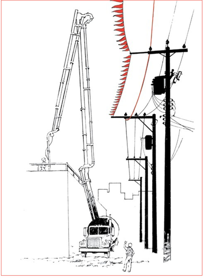
Guarding is a visual warning only. The grounded guard wire (with flags) gives a warning of approach. The overhead line cover-ups, installed by the owner of the power system, have no insulated rating. Workers and equipment must not contact the guards or overhead line under any circumstances. Serious injuries or death can result if any part of a crane touches a power line.
Recertifying Equipment After Electrical Contact
When a machine contacts a power line, the passage of current through the machine can impair the strength of some of its parts. Any hoisting or aerial device that has contacted an energized conductor must be recertified by a professional engineer before it is returned to service. It is recommended that a licensed mechanic check other mobile equipment that has contacted a power line.
Construction Sites Near Power Lines
Each year workers in many places die or are seriously burned as a result of unsafe work practices around energized conductors. The following information is a reminder to operators of construction equipment and to construction and maintenance workers who must work near power lines:
• Most power lines are found overhead; however, some are buried just a short distance below the surface of the
• The normal operating range of your machine or equipment can often reach either the overhead or the underground power lines above or below
• Supervisors and operators of equipment can prevent electrical accidents through knowledge of electrical systems and safe work

Mobile Equipment Near Power Lines
Operators of mobile equipment such as cranes, hoists, and backhoes must take care that no part of the equipment makes contact with an overhead power line. If any part of the equipment contacts an overhead power line, remember that the operator is safer inside the machine than on the ground. If mobile equipment touches a power line, electricity can travel from the power line to a worker touching any part of the equipment, including a pendant control.
A worker was on the ground guiding a mobile crane onto a truck deck when the crane’s boom contacted a power line. The electrical current passed through the crane jib that the worker was holding and then passed through the worker to the ground. The worker was electrocuted.
In another accident, a pumper truck operator was lowering the truck’s boom after pouring concrete. He was standing away from the truck using the pendant control. The boom contacted the high-voltage line and power came through the pendant line to the operator. The operator was electrocuted.
If you operate mobile equipment near power lines, take the following precautions:
1. Keep your mobile equipment, work materials, and tools at a safe distance from power lines. This is your first line of defense when operating mobile equipment near overhead power lines.
2. If it is necessary to operate equipment closer than 6 m (20 ft.) to a power line, contact the owner of the power system to find out the voltage of the line. Then find the minimum distance away from the line you are allowed to work. If it is not possible to keep this distance, the owner of the power system may need to de-energize or reroute the circuit, or provide guarding. Don’t proceed until the owner of the power system has given written assurance defining proper
3. Don’t stand on the ground beside your machine to operate the remote controls for the equipment. If a power line contact occurs, current will flow through the machine to the ground. If your feet are on the ground and you touch the electrified machine, current will pass through your body to the ground. An electrical contact will also energize the ground around the machine for some distance, up to at least 10 m (33 ft.) — more if the lines carry voltages higher than 60 kV (60,000 V).
4. If you must operate controls from the ground, the remote control signal should be carried by radio or non-conductive cable such as fiber. If the fiber optic cable has armored with metal bands, it will be conductive. In addition, you should stand well clear when operating equipment with a remote control - depending on the voltage, at least 10 m (33 ft.) away from your machine and the power lines.
Traveling Under Power Lines
Know the height of your load and the height of the power lines you will be traveling under. Always make sure there is sufficient clearance for your load to travel safely under the power lines.
Hazard Alert
The height of all mobile equipment must be minimized before transporting near high voltage lines, for example the boom of a grapple yarder must been lowered for transport.
Pruning or Falling Trees Near Power Lines
Workers have been killed or injured when doing tree care work or falling trees near power lines. Before workers prune or fall trees close to a power line, a qualified person must inspect the worksite to identify any hazards, including situations where any part of a tree is within the general limits of approach or could fall within that distance. The owner of the power system must authorize the person doing the inspection and ensure that the person is qualified.
If tree pruning or falling will come within the general limits of approach, workers must be authorized by the owner of the power system to do the work. Normally the only worker authorized to do this work will be a qualified electrical worker, a certified utility arborist, or an apprentice utility arborist working under the direct supervision of a certified utility arborist or a qualified electrical worker.
Tree pruning or falling is not allowed within the general limits of approach unless both of the following are true:
1. A certified utility arborist or qualified electrical worker is present at the site and directing the work
2. At least one additional qualified person, trained in appropriate emergency rescue, is present
A Working Example
A tree trimmer was up in a tree trimming branches about 2.5 m (8 ft.) away from a power line. When he cut a tree branch, it fell onto the power line and the other end hung against the trunk of the tree. The worker received a fatal shock when he tried to free the branch from the tree.
Scaffolds and Other Equipment Near Power Lines
The limits of approach must be maintained for all scaffolds and equipment near power lines. For example, workers on scaffolds or window-washing platforms must not let any tools, such as pipes or rollers, come within the limits of approach. Scaffolds must be positioned and secured in a manner to prevent them from coming into contact with adjacent power lines.
Farm equipment can cause accidents when it contacts power lines. Farm workers have been electrocuted when metal irrigation pipes have been lifted up, touching overhead power lines. Where practicable, store metal irrigation pipes at least 30 m (100 ft.) away from overhead power lines.
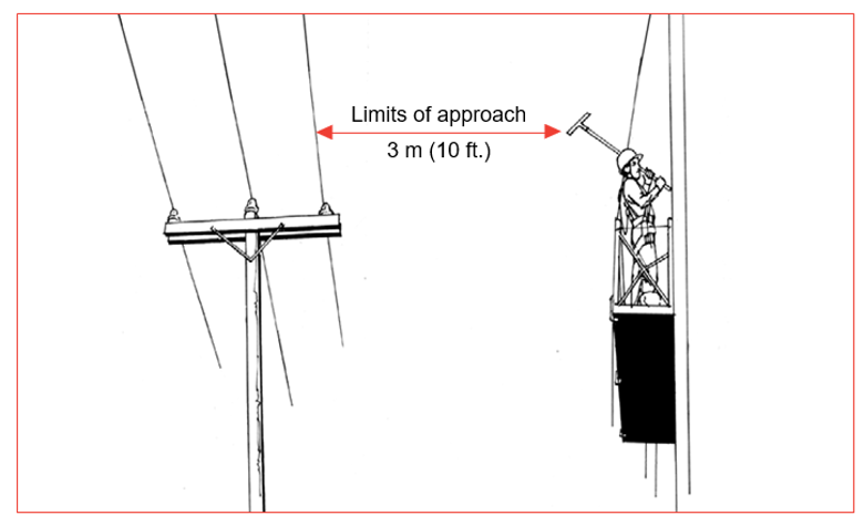
A tool is an extension of your reach and must not come within the limits of approach. A construction worker was erecting tubular scaffolding 3 m (10 ft.) from an energized 25 kV (25,000 V) conductor. The worker was handling a long section of bracing, which accidentally contacted the power line. The worker was electrocuted.

A worker was excavating a trench beside a utility pole. The pole was undermined when too much soil was removed next to the pole. The pole fell over, causing high-voltage lines to fall near the worker. Fortunately, the worker was not injured.
Utility poles
Don’t work close to utility poles if the work could cause a pole to become unstable or if you can’t maintain the limits of approach. If any poles are unstable, ask the owner of the power system to support or remove them. Workers must not climb poles supporting power lines unless they are qualified and authorized by the owner of the utility.
Underground utilities

Low-voltage and high-voltage underground wiring is used for supplying power to schools, commercial buildings, homes, and numerous other sites. Drilling, excavating, or probing can be dangerous near buried electrical lines. Check with the owner of the power system for the existence and location of underground lines before you start digging.
Workers have died because their shovel blade penetrated a live high- voltage electrical cable. A treated-wood plank buried on top of the cable may be the only protection for the cable. Modern installations often have a bright yellow plastic ribbon buried below the surface to warn that a cable lies beneath it. “Danger — High Voltage” signs warn that high-voltage equipment is enclosed inside and buried underground. Don’t take chances — contact the owner of the power system before you start digging. You must accurately identify the location of underground utilities before you dig. Besides electricity, there are other kinds of underground utilities, including telephone, gas, cable, water, and pipeline services.
Find Out the Locations of any Underground Cables
Before You Begin Work
The following activities are potentially hazardous because workers may contact buried power lines:
• Driving ground rods or any other long metal objects into the ground
• Digging holes for fence posts
• Digging near “Danger — High Voltage” signs
• Trenching

Locate Cables First
A worker was breaking concrete when his jackhammer broke through a conduit. The tool contacted an energized 15 kV (15,000 V) underground cable. The worker was electrocuted.
Conclusion
3 Keys of Electrical Safety
1. Look up and down.
All workers who operate machinery or equipment that could come in contact with power lines should look up and check for overhead power lines before beginning work or identify underground power lines in the vicinity. Plan your work to prevent electrical contact.
2. Keep back — Know your limits.
When operating machinery or equipment in close proximity to power lines, always maintain the limits of approach: 3–6 m (10–20 ft.), depending on the voltage. Use a spotter to make sure you keep equipment away from power lines.
Where any portion of a machine or equipment may come closer than the minimum distance, contact the power system owner to provide some form of protection.
On the ground stay at least 10 m (33 ft.) away from operating equipment because if it contacts an energized line the electricity will go to ground. The operator should be on the vehicle with everyone else clear of the vehicle when the boom is in motion. If you must approach, ensure the equipment is not operating.
3. Stay back, and call for help.
Stay back at least 10 m (33 ft.) from a fallen power line, exposed underground power line, or any object in contact with the line. If the machinery you are operating contacts an energized line, move it away from the line to break contact. If you can’t do this, stay put in the machine until help arrives.
If it’s a life-threatening situation such as a fire, jump clear of the machine, keeping your feet together. Never contact the machine and the ground at the same time. Once clear of the machine, shuffle away, never allowing the heel of one foot to move beyond the toe of the other. Keep shuffling until you are at least 10 m (33 ft.) away from the machine; this is the safe distance for voltages up to and including 60kV (60,000 V).
Depending on the voltage, you may need to get as much as 32 m (105 ft.) away from the machine.
Always call your local emergency services when someone is injured in an electrical accident. Don’t attempt a rescue until directed by qualified personnel. If you touch an injured person who is still in contact with an electrical source, you could be seriously injured or killed. Keep everyone back at least 10 m (33 ft.), and have someone call for help immediately.
Blog #3 - PPE (Personal Protective Equipment)
/Electrical Safety
and
PPE (Personal Protective Equipment)
Introduction
Electrical safety is one of the most important aspects of electrical work. During my career in the electrical power utility industry, this fact was indelibly imprinted on my mind, which not only helped me on the job, but off the job as well. I do believe that repetition was the key. So, on this site and in these blogs, you’ll find a return to this subject matter often. Because this site, my courses and this blog, reaches thousands of students internationally, I’m going start off with my first safety blog with seemingly a simplistic approach, but after I set the foundation, I will move on to more sophisticated safety topics in later posts.
Electrical professionals must follow all local, state, and federal regulations when they are working with electricity. There are several items of PPE (Personal Protective Equipment) that electrical professionals must wear in order to protect themselves and others.
There are several items of PPE Personal Protective Equipment that electrical professionals must wear in order to protect themselves and others.

PPE Personal Protective Equipment is required by law, and is essential to the safety of people working on electrical equipment. The following types of PPE must be worn at all times:
Rubber-soled shoes or boots
Leather work gloves (insulated)
Protective clothing covering the arms, legs, and torso (this may or may not include fire retardant material)
Electrical professionals must also wear their hard hat in addition to these items.
A hard hat is a very important piece of protective equipment

Gloves protect the hands from the elements, cuts, scrapes, and in some cases serious burns

Boots help to protect your feet from falling objects and also from electrocution.

Boots can help to protect your feet from falling objects and also from electrocution.
Electrical safety is important.
Boots should be made of leather or rubber, insulated, and high enough to protect your ankles. They should also be non-conductive (electrical resistive).